Arduino: Unterschied zwischen den Versionen
Stefan (Diskussion | Beiträge) (→Arduino Multifunktions- Sensorplatine) |
Stefan (Diskussion | Beiträge) (→Multi Funktions Shield) |
||
| Zeile 312: | Zeile 312: | ||
Unser Muli-Function Shield für den Arduino bietet folgende Funktionen: | Unser Muli-Function Shield für den Arduino bietet folgende Funktionen: | ||
| − | 4 LED-Anzeige D1, D2, D3, D4 | + | 4 LED-Anzeige D1, D2, D3, D4 |
| − | Integrierter Infrarot-Empfänger | + | Integrierter Infrarot-Empfänger |
| − | 3 x Push Taster, 1 x Reset-Taste | + | 3 x Push Taster, 1 x Reset-Taste |
| − | 1 x 3296 Potentiometer | + | 1 x 3296 Potentiometer |
| − | 1x Buzzer | + | 1x Buzzer |
| − | 1x Anschlusssockel für Dallas DS18B20 | + | 1x Anschlusssockel für Dallas DS18B20 |
| − | 1x Anschlusssockel für LM35 | + | 1x Anschlusssockel für LM35 |
| − | 1x 4 Ziffern 7 Segment Anzeige über 74HC595 | + | 1x 4 Ziffern 7 Segment Anzeige über 74HC595 |
http://www.cohesivecomputing.co.uk/hackatronics/arduino-multi-function-shield/ | http://www.cohesivecomputing.co.uk/hackatronics/arduino-multi-function-shield/ | ||
Version vom 16. September 2021, 23:02 Uhr
Willkommen auf unserer Arduino Wiki Seite
Inhaltsverzeichnis
- 1 AVR Checkliste
- 2 Meine Arduino-Projekte
- 3 AVR-Tutorial: IO-Grundlagen
- 4 Typen
- 5 MySensors
- 6 Simulator
- 7 Tutorial
- 8 Funduino
- 9 Foren
- 10 Webseite
- 11 Arduino Praxis
- 12 Miniblog
- 13 AskSin
- 14 Arduino Shields
- 14.1 Arduino Shieldlist
- 14.2 http://www.stall.biz/
- 14.3 Display
- 14.4 Ethernet Shield
- 14.5 Servo
- 14.6 WiFi
- 14.7 easyVR Shield
- 14.8 mSD Shield
- 14.9 RGB Shield
- 14.10 IO Shield KA05
- 14.11 LCD keyPad
- 14.12 RPI Arduino Shield
- 14.13 SIM908
- 14.14 Danger Shield v1.0
- 14.15 Realtime DCF
- 14.16 MotorShield
- 14.17 DK I/O Expansion Shield 5.0
- 14.18 XBee Shield V 3.0
- 14.19 Busware CC1101 Shield
- 14.20 Joystick-Shield
- 14.21 Multi Funktions Shield
- 14.22 Arduino Multifunktions- Sensorplatine
- 14.23 TM1638 LED & Key
- 14.24 CAN Bus Shield
- 14.25 KS0411_keyestudio_CAN-BUS_Shield
- 14.26 Prototype Shield V5 Arduino UNO + Gratis Breadboard Protoshield Erweiterung
- 14.27 Prototype Shield Arduino Mega + Gratis Mini Breadboard Erweiterung ProtoShield
- 15 Treiber
- 16 USB
- 17 Temboo
- 18 Librarys
- 19 Projekte
AVR Checkliste
https://www.mikrocontroller.net/articles/AVR_Checkliste
Meine Arduino-Projekte
https://arduino-projekte.webnode.at/
AVR-Tutorial: IO-Grundlagen
https://www.mikrocontroller.net/articles/AVR-Tutorial:_IO-Grundlagen
Typen
UNO


UNO SMD


Leonardo


Diecimila


Nano


Pro Mini


Netduino


Web
http://netduino.com/
Wiki
https://en.wikipedia.org/wiki/Netduino
AZ-ENVY ESP 8266

Beschreibung
AZ-Envy ist ein auf dem ESP8266-12F basierendes Entwicklerboard, speziell für den einfachen Einstieg in die Welt des IoT.
Das Board bietet eine Vielzahl von Einsatzmöglichkeiten für Maker, Hobby-Bastler und Ingenieure, wie z.B. den Einsatz als Wetterstation mit
Datentransfer zu Google Firebase, Gaszähler, Schimmelpilzschutz, Gartenhausüberwachung und vieles mehr.

Messung von Temperatur (° C) und Luftfeuchtigkeit (%)
Messung von Umgebungsgasen und Luftqualität in ppm
variable Spannungsversorgung von 3V bis 11V über Micro USB
Programmierung über FTDI-Schnittstelle
ESP8266-12F Chip:
802.11b/g/n Wi-Fi-SOC-Modul mit stromsparendem 32-Bit-CPU (Standby 0,02mA) und mit bis zu 160MHz Taktfrequenz
eingebauter hochpräziser 10-Bit-ADC
Programmierbar über ein FTDI Interface oder mit den Knöpfen auf dem Modul (RESET und FLASH gedrückt halten)
MQ-2 Sensor:
Anstieg der Leitfähigkeit bei erhöhter Gaskonzentration
Dank seiner hohen Empfindlichkeit ideal einsetzbar als häuslicher Gasleck-Detektor, als tragbarer Gasdetektor oder zum messen brennbarer Gase
lange Lebensdauer und niedrige Kosten
Temperatur- und Feuchtigkeitssensor SHT30:
Genauigkeit der relativen Luftfeuchtigkeit ±2%
Temperaturgenauigkeit ±0,2°C
14 Bit Messauflösung
I2C-Schnittstelle (angeschlossen an SDA und SCL)
miguel5612 MQSensorsLib Library
https://github.com/miguel5612/MQSensorsLib
Tasmota
https://technik.katzenjens.de/2021/05/az-envy-umweltsensor-mit-tasmota.html
Attiny85

http://www.max-mg.de/Digispark_ATTiny85_einrichten.pdf

http://digistump.com/wiki/digispark/tutorials/connecting
MySensors
https://www.mysensors.org/
Tipps
gw.begin(incomingMessage, 101, false);
RFID
https://forum.mysensors.org/topic/2439/rfid-garage-door-opener

Display
https://forum.mysensors.org/topic/2360/temperature-humidity-node-with-oled-display
https://forum.mysensors.org/topic/2719/text-node-as-temperature-display/2
Arduino
https://forum.fhem.de/index.php/topic,31663.0.html
https://forum.fhem.de/index.php/topic,37166.0.html
https://forum.fhem.de/index.php/topic,28198.0.html
https://forum.fhem.de/index.php/topic,31400.0.html
Simulator
https://www.sites.google.com/site/unoardusim/home

https://xevro.be/products/arduino%20simulator%201.5.html
Tutorial
http://www.arduino-tutorial.de/
http://www.arduino-tutorial.de/inhaltsverzeichnis/
http://technik-garage.de/mikrocontroller/darum-arduino-uno/
http://popovic.info/html/arduino/arduinoUno_1.html
Funduino
https://www.funduinoshop.com/epages/78096195.sf/de_DE/?ObjectPath=/Shops/78096195
Foren
http://www.arduinoforum.de/index.php
https://forum.arduino.cc/
Webseite
Arduino Praxis
Miniblog
AskSin
https://github.com/trilu2000/AskSin
https://github.com/trilu2000/NewAskSin
http://www.fhemwiki.de/wiki/HomeMatic_Asksin_Library

https://forum.fhem.de/index.php?topic=14140
Arduino Shields
Arduino Shieldlist
http://www.stall.biz/
http://www.stall.biz/
Display
3.5inch Arduino Display-UNO
http://www.lcdwiki.com/3.5inch_Arduino_Display-UNO#Reference_Materials
Ethernet Shield

Daten über URL senden und empfangen
http://arduino.stackexchange.com/questions/10410/how-to-call-url-with-arduino-ethernet-shield
http://www.arduinoforum.de/arduino-Thread-Daten-per-Ethernet-Shield-2-senden?highlight=FHEM
Beispiele
https://github.com/bmericc/arduino-projects/blob/master/rfid-ethernet/rfid-ethernet.ino
https://www.stall.biz/project/homeduino-der-universelle-lanwlan-arduino-fur-die-hausautomation/comment-page-1
http://haacking.de/laser-analytics/
http://www.fhemwiki.de/wiki/Arduino_Firmata
http://homematic-forum.de/forum/viewtopic.php?f=31&t=15397
http://www.arduinoforum.de/arduino-Thread-GET-URL-zusammenbauen
http://uweziegenhagen.de/?p=2830
http://interactive-matter.eu/how-to/arduino-http-client-library/
http://stackoverflow.com/questions/7071563/library-to-parse-http-responses-with-arduino
http://playground.arduino.cc/Code/WebClient
Servo
16 Channel Servo Driver
https://learn.adafruit.com/16-channel-pwm-servo-driver

WiFi
RedFly
http://www.watterott.com/de/Arduino-RedFly-Shield

easyVR Shield
http://www.veear.eu/

mSD Shield

http://www.watterott.com/de/Arduino-mSD-Shield
http://www.watterott.com/de/MI0283QT-2-Adapter


RGB Shield
 Vellemann VA01

IO Shield KA05
 Vellemann IO Shield KA05

LCD keyPad
http://www.dfrobot.com/wiki/index.php/Arduino_LCD_KeyPad_Shield_(SKU:_DFR0009)
http://www.instructables.com/id/Arduino-LCD/

RPI Arduino Shield

http://www.watterott.com/de/RPi-ShieldBridge


SIM908
https://www.cooking-hacks.com/gprs-gps-quadband-module-for-arduino-sim908

Danger Shield v1.0


http://www.zachhoeken.com/danger-shield-v1-0
http://www.zachhoeken.com/connecting-to-the-world
https://sourceforge.net/projects/dangershield/files/Danger%20Firmware/
http://wiki.seeed.cc/Danger_Shield_Complete_Kits/
Realtime DCF
http://www.elv.de/real-time-clock-dcf-modul-mit-i2c-spi-u-uart-schnittstelle-rtc-dcf-bausatz.html

MotorShield
Motor Control Shield


Arduino Motor Driver Shield
A Motor driver shield for Arduino boards that can control up to 4 bi-directional DC motors with individual 8-bit speed selection, or 2 stepper motors (unipolar or bipolar) with single coil, double coil, interleaved or micro-stepping. 2 connections for 5V 'hobby' servos connected to the Arduino's high-resolution dedicated timer - no jitter!
The shield contains two L293D motor drivers and one 74HC595 shift register. The shift register expands 3 pins of the Arduino to 8 pins to control the direction for the motor drivers. The output enable of the L293D is directly connected to PWM outputs of the Arduino.
To increase the maximum current, the L293D allows extra chips with "piggyback". Piggyback is soldering one or two or three extra L293D drivers on top of the L293D drivers on the board to increase the maximum current. The L293D allows parallel operation.
Features:
Supplied Fully Assembled
2x 5V Servo outputs connected to the high-resolution dedicated timer - no jitter!
Can drive 4 DC motors or 2 stepper motors or 2 Servo's
Up to 4 bi-directional DC motors with individual 8-bit speed selection
Up to 2 stepper motors (unipolar or bipolar) with single coil, double coil or interleaved stepping.
4 H-Bridges: per bridge provides 0.6A (1.2A peak current) with thermal protection, can run motors on 4.5V to 36V DC
Pull down resistors keep motors disabled during power-up
reset button
Tested compatible for Mega, Diecimila, Duemilanove, UNO
Power Supply
Power for the motors can be supplied from the Arduino boards DC Jack (normally 9V) or from the 2-pin EXT-PWR terminal block.
If you are supplying power from the EXT_PWR terminal block you should remove the PWR jumper or you could damage the shield and the Arduino board.
https://www.hobbytronics.co.uk/arduino-motor-shield
https://playground.arduino.cc/Main/AdafruitMotorShield/
https://www.instructables.com/Arduino-Motor-Shield-Tutorial/
Keyestudio TB6612FNG

The parameters of keyestudio TB6612FNG motor/servo drive expansion board are as follows:
VIN voltage: VIN = DC 7-15V
VIN current: 5A
Two-way 5V output: 5V/3A
TB6612FNG: VIN input DC 7-15V; average drive current 1.2A; peak current 3.2A
PS2 interface: compatible with Sony PS2 receiver, can be plugged directly into the expansion board.
Dimensions: 73*53.34mm
https://wiki.keyestudio.com/KS0489_Keyestudio_4WD_TB6612_Motor_Driver_Shield_(Black_and_Eco-friendly)
Deek Robot Motor Shield V1
https://coderdojo-robots.readthedocs.io/en/latest/motor-direction-testing/

DK I/O Expansion Shield 5.0
http://www.dfrobot.com/wiki/index.php/IO_Expansion_Shield_For_Arduino(V5)_(SKU:_DFR0088)

XBee Shield V 3.0
http://mcukits.com/2009/03/12/assembling-the-nkc-electronics-xbee-shield-v30-kit/
http://mcukits.com/category/xbee-shield-for-arduino/
http://forums.nkcelectronics.com/viewforum.php?f=24

Busware CC1101 Shield
http://busware.de/tiki-index.php?page=ARDCSM

Joystick-Shield
https://www.sparkfun.com/products/9760
http://www.watterott.com/de/Joystick-Shield-Kit

Multi Funktions Shield
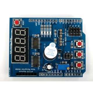

Tolle Erweiterungskarte für den Arduino Uno oder Mega. Einfach Aufstecken und über eine Vielzahl von neuen Funktionen verfügen. Für viele Projekte lassen sich sicherlich die 3 Push Taster, die Led-Anzeige, der Potentiometer oder auch der DS18B20 Adapter ausgezeichnet nutzen.
Unser Muli-Function Shield für den Arduino bietet folgende Funktionen:
4 LED-Anzeige D1, D2, D3, D4
Integrierter Infrarot-Empfänger
3 x Push Taster, 1 x Reset-Taste
1 x 3296 Potentiometer
1x Buzzer
1x Anschlusssockel für Dallas DS18B20
1x Anschlusssockel für LM35
1x 4 Ziffern 7 Segment Anzeige über 74HC595
http://www.cohesivecomputing.co.uk/hackatronics/arduino-multi-function-shield/
http://arduinolearning.com/code/multi-function-shield-examples.php
Arduino Multifunktions- Sensorplatine
.jpg)
https://www.fambach.net/arduino-multi-sensor-platine/
TM1638 LED & Key

Technische Daten:
Spannungsversorgung: 5 Volt
8 x rote LEDs
8fach 7-Segment Anzeige
8 x Taster
Pin-Belegung:
VCC -> +5V
GND -> GND
STB -> PIN A7 2 11
CLK -> PIN A8 3 12
DIO -> PIN A9 4 13
https://robotfreak.de/elab-wiki/index.php?title=LED-Key_Board
https://robotfreak.de/elab-wiki/index.php?title=LED-Key_Modul_am_Arduino
https://www.instructables.com/Arduino-and-TM1638-LED-Display-Modules/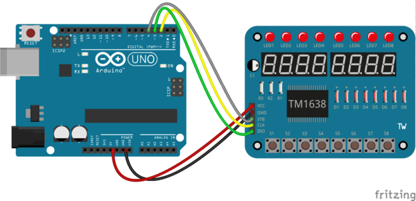

TM1638plus
https://github.com/gavinlyonsrepo/TM1638plus

From TM1638plus.h
Constructor
Parameters
1. strobe = GPIO STB pin
2. clock = GPIO CLK  pin
3. data = GPIO DIO pin
4. higfreq Changes the value of parameter _HIGH_FREQ which is default false
This is used when running high freq MCU CPU (~>100Mhz) because of issues with button function.
Pass true when running high freq MCU CPU (~>100Mhz).
TM1638plus(uint8_t strobe, uint8_t clock, uint8_t data, bool highfreq = false);
Methods
void displayBegin();	 // Begin method , sets pinmodes , Call in setup
void reset(void);  // Reset / Clear module
Sets the brightness level on a scale of brightness = 0 to 7.
0 is not turned off, it's just the lowest brightness.
If user wishes to change the default brightness at start-up change.
The DEFAULT_BRIGHTNESS define in header file.
void brightness(uint8_t brightness);
Read buttons returns a byte with value of buttons 1-8 b7b6b5b4b3b2b1b0
1 pressed, zero not pressed.
User may have to debounce buttons depending on application.
See [URL LINK](https://github.com/gavinlyonsrepo/Arduino_Clock_3) for de-bonce example.
uint8_t readButtons(void);
Send Text to Seven segments, passed char array pointer dots are removed from string and dot on preceding digit switched on "abc.def" will be shown as "abcdef" with c decimal point turned on.
void displayText(const char *text);
Send ASCII value to seven segment, pass position 0-7 and ASCII value byte
void displayASCII(uint8_t position, uint8_t ascii);
Same as displayASCII function but turns on dot/decimal point  as well
void displayASCIIwDot(uint8_t position, uint8_t ascii) ;
Send HEX value to seven segment, pass position 0-7 and hex value(DEC) 0-15
void displayHex(uint8_t position, uint8_t hex);
Send seven segment value to seven segment pass position 0-7 byte of data corresponding to segments (dp)gfedcba i.e 0b01000001 will set g and a on.
void display7Seg(uint8_t position, uint8_t value);
Display an integer and leading zeros optional
void displayIntNum(unsigned long number, boolean leadingZeros = true);
Divides the display into two nibbles and displays a Decimal number in each.
takes in two numbers 0-9999 for each nibble ,  and byte for decimal point display, and leading zeros optional
void DisplayDecNumNibble(uint16_t numberUpper, uint16_t numberLower, boolean leadingZeros = true);
Set the LEDs. passed one  16bit integer.
MODEL 3:
MSB byte for the green LEDs, LS byte for the red LEDs (0xgreenred)
ie. 0xE007   1110 0000 0000 0111   results in L8-L0  GGGX XRRR, NOTE L8 is RHS on display
MODEL 1:
MSB byte 1 for  red LED , LSB byte n/a set to 0x00 (0xleds, 0xXX)
i.e 0xF100  1111 0000 L8-L0 RRRRXXX0 NOTE  L8 is RHS on display
void setLEDs(uint16_t greenred);
Set an LED, pass it LED position 0-7 and value 0 or 1 , L1-L8
void setLED(uint8_t position, uint8_t value);
==== TM1638lite ====
https://github.com/danja/TM1638lite
From TM1638.h :
TM1638lite (uint8_t strobe, uint8_t clock, uint8_t data)
void reset () clear the TM1638 - use in setup()
uint8_t readButtons () bits in returned value correspond to state of buttons
void setLED (uint8_t position, uint8_t value) turns LED at position on (value=1) or off (value=0)
void displayText (String text) displays an approximation of the text on the 7-segment display
void displaySS (uint8_t position, uint8_t value) direct access to 7-segment display at position, bits of value state which segments to turn on
void displayASCII (uint8_t position, uint8_t ascii) displays an approximation of the ASCII character at position
void displayHex (uint8_t position, uint8_t hex) displays a hex representation of the value at position
void sendCommand (uint8_t value) send low-level command, probably won't be needed
CAN Bus Shield
Library
https://github.com/sparkfun/SparkFun_CAN-Bus_Arduino_Library
https://github.com/sparkfun/CAN-Bus_Shield
https://github.com/Seeed-Studio/CAN_BUS_Shield
MCP 2515 CAN Shield


https://github.com/Seeed-Studio/CAN_BUS_Shield
https://www.electronicshub.org/arduino-mcp2515-can-bus-tutorial/
MCP2515 EF02037 CAN BUS Shield Arduino communication speed high SPI Controller
.jpg)
Introduction:
CAN-BUS is a common industrial bus because of its long travel distance, medium communication speed and high reliability.
It is commonly found on modern machine tools and as an automotive diagnostic bus.
This CAN-BUS Shield adopts MCP2515 CAN Bus controller with SPI interface and MCP2551 CAN transceiver to give your Arduino/Seeeduino CAN-BUS capibility.
With an OBD-II converter cable added on and the OBD-II library imported, you are ready to build an onboard diagnostic device or data logger.
Features:
Implements CAN V2.0B at up to 1 Mb/s
SPI Interface up to 10 MHz
Ariduino/ Freaduino Completely compatible
Standard (11 bit) and extended (29 bit) data and remote frames
Industrial standard 9 pin sub-D connector
Two receive buffers with prioritized message storage
Operating voltage: DC5-12V
Size: 78mmx53.5m
https://www.seeedstudio.com/blog/2019/11/27/introduction-to-can-bus-and-how-to-use-it-with-arduino/
https://www.seeedstudio.com/blog/2020/06/05/mcp2515-can-bus-arduino-tutorial-getting-started-interfacing-applications/
https://wiki.seeedstudio.com/CAN-BUS_Shield_V2.0/
https://community.seeedstudio.com/project_detail.html?id=291

https://learn.sparkfun.com/tutorials/can-bus-shield-hookup-guide
https://hackaday.io/project/6288-can-bus-gaming-simulator
https://hackaday.com/2015/06/18/a-real-dash-for-a-truck-simulator/
KS0411_keyestudio_CAN-BUS_Shield
.jpg)
Das keyestudio CAN-BUS Shield wurde speziell für Arduino-Controller entwickelt.
Der Onboard-Bus-Steuerchip kann die Datensteuerung auf dem CAN-Bus realisieren, um die Datenkommunikation zwischen Geräten zu realisieren.
Es ist mit der Arduino UNO-Standardschnittstelle kompatibel. kann perfekt an die Hauptsteuerplatinen wie Arduino UNO und Leonardo angepasst werden.
Die Abschirmung verfügt über einen DB9-Anschluss, sodass Sie die Schnittstelle gemäß Ihren Anforderungen auswählen können.
Es ist auch mit einem MicroSD-Kartensteckplatz ausgestattet, sodass Sie die MicroSD-Karte direkt zum Speichern von Daten einsetzen können.
Mithilfe verschiedener Erweiterungsschnittstellen können Benutzer den DIY-Prozess komfortabler gestalten.

Technische Parameter
Betriebsspannung: DC5V
Chip: MCP2515
Abmessungen: 66 mm * 54 mm * 28 mm
Gewicht: 24g
Umweltattribut: ROHS
https://wiki.keyestudio.com/KS0411_keyestudio_CAN-BUS_Shield
Prototype Shield V5 Arduino UNO + Gratis Breadboard Protoshield Erweiterung

Das Prototype Shield ist ausgestattet mit 2 LEDs, Drucktaste und Widerstand. Es ist kompatibel mit Arduino UNO und lässt sich ganz einfach aufstecken. So können Sie Ihr Projekt direkt auf einem Shield für Ihren Arduino entwickeln. Das mitgelieferte Breadboard hat 170 Pins und passt perfekt auf das Protoshield.
Prototype Shield Arduino Mega + Gratis Mini Breadboard Erweiterung ProtoShield

Das Prototype Shield V3 ist ausgestattet mit 2 LEDs, Drucktaste und Widerstand. Es ist kompatibel mit Arduino MEGA und lässt sich ganz einfach aufstecken. So können Sie Ihr Projekt direkt auf einem Shield für Ihren Arduino entwickeln. Das mitgelieferte Breadboard hat 170 Pins und passt perfekt auf das Protoshield.
Treiber
http://www.zweiradforum24.de/364-arduino-nano-mit-ch340-chip-unter-windows-7-64bit/
http://shelvin.de/arduino-dccduino-usb-treiber-installieren/
USB
http://electronics.stackexchange.com/questions/110904/wiring-arduino-mini-pro-with-cp2102-usb-to-ttl
http://lab.dejaworks.com/programming-arduino-mini-pro-with-cp2102-usb-to-ttl-serial-converter/
Temboo
https://temboo.com/arduino
Librarys
Webconfig
https://github.com/GerLech/WebConfig/blob/master/README.md
TFT
https://github.com/adafruit/Adafruit_ILI9341

https://github.com/adafruit/Adafruit-GFX-Library/blob/master/Adafruit_GFX.h

https://github.com/PaulStoffregen/XPT2046_Touchscreen
#include "SPI.h"
#include "Adafruit_GFX.h"
#include "Adafruit_ILI9341.h"
// For the Adafruit shield, these are the default.
#define TFT_DC 9
#define TFT_CS 10
/*__Pin definitions for the ESP8266__*/
#define TFT_CS   5
#define TFT_DC   4
#define TFT_LED  15
#define TFT_MOSI 23
#define TFT_CLK  18
#define TFT_RST  22
#define TFT_MISO 19
#define TFT_LED  15
#define HAVE_TOUCHPAD
#define TOUCH_CS 14
#define TOUCH_IRQ 27
// Use hardware SPI (on Uno, #13, #12, #11) and the above for CS/DC
Adafruit_ILI9341 tft = Adafruit_ILI9341(TFT_CS, TFT_DC);
// If using the breakout, change pins as desired
//Adafruit_ILI9341 tft = Adafruit_ILI9341(TFT_CS, TFT_DC, TFT_MOSI, TFT_CLK, TFT_RST, TFT_MISO);
tft.begin();
// read diagnostics (optional but can help debug problems)
uint8_t x = tft.readcommand8(ILI9341_RDMODE);
Serial.print("Display Power Mode: 0x"); Serial.println(x, HEX);
x = tft.readcommand8(ILI9341_RDMADCTL);
Serial.print("MADCTL Mode: 0x"); Serial.println(x, HEX);
x = tft.readcommand8(ILI9341_RDPIXFMT);
Serial.print("Pixel Format: 0x"); Serial.println(x, HEX);
x = tft.readcommand8(ILI9341_RDIMGFMT);
Serial.print("Image Format: 0x"); Serial.println(x, HEX);
x = tft.readcommand8(ILI9341_RDSELFDIAG);
Serial.print("Self Diagnostic: 0x"); Serial.println(x, HEX);
tft.setRotation(1);
iquidCrystal-I2C
https://github.com/fdebrabander/Arduino-LiquidCrystal-I2C-library
https://github.com/marcoschwartz/LiquidCrystal_I2C

http://www.nikolaus-lueneburg.de/2016/02/new-liquidcrystal-library/
https://bitbucket.org/fmalpartida/new-liquidcrystal/wiki/Home#!downloading-and-installation
https://sminghub.github.io/sming-api-develop/classLiquidCrystal__I2C.html

https://www.makerguides.com/character-i2c-lcd-arduino-tutorial/
https://github.com/johnrickman/LiquidCrystal_I2C
//YWROBOT
//Compatible with the Arduino IDE 1.0
//Library version:1.1
#include <Wire.h>
#include <LiquidCrystal_I2C.h>
LiquidCrystal_I2C lcd(0x27,20,4);  // set the LCD address to 0x27 for a 16 chars and 2 line display
LiquidCrystal_I2C lcd(0x3F,16,4);  // set the LCD address to 0x27 for a 16 chars and 2 line display
void setup()
{
lcd.init();                      // initialize the lcd
// lcd.init();
// Print a message to the LCD.
lcd.setBacklight(1);
lcd.setCursor(0,0);
lcd.print("Hello, world!");
lcd.setCursor(0,1);
lcd.print("Ywrobot Arduino!");
}
Tutorial: Erstellen einer Arduino-Bibliothek
http://www.roboternetz.de/community/threads/65187-Tutorial-Erstellen-einer-Arduino-Bibliothek
Arduino-MQTT
https://github.com/256dpi/arduino-mqtt
FHEM_Arduino
https://github.com/kingmathers313/FHEM_Arduino
FHEM fhemclient("http://192.168.1.1:8083/fhem", "User", "Password");
String result = fhemclient.LoadFromServer("{SomeSub()}");
sub SomeSub
{
my $response = Value("WaschmaschineDummy");
$response = "Waschmaschine\nStatus: " . $response;
return $response;
}
ESP8266_FHEM_Display
https://github.com/kingmathers313/ESP8266_FHEM_Display
Projekte
forbiddenbit
Arduino Oszi
http://forbiddenbit.com/466/