ESP 8266: Unterschied zwischen den Versionen
Stefan (Diskussion | Beiträge) (→Code) |
Stefan (Diskussion | Beiträge) (→Init) |
||
| Zeile 249: | Zeile 249: | ||
====== Init ====== | ====== Init ====== | ||
#include <Adafruit_NeoPixel.h> | #include <Adafruit_NeoPixel.h> | ||
| − | |||
#include "SH1106.h" | #include "SH1106.h" | ||
#define BUTTON_PRESS 18 | #define BUTTON_PRESS 18 | ||
| Zeile 262: | Zeile 261: | ||
SH1106 display(0x3c,17,16); | SH1106 display(0x3c,17,16); | ||
Adafruit_NeoPixel strip = Adafruit_NeoPixel(PIXEL_COUNT, PIXEL_PIN, NEO_GRB + NEO_KHZ800); | Adafruit_NeoPixel strip = Adafruit_NeoPixel(PIXEL_COUNT, PIXEL_PIN, NEO_GRB + NEO_KHZ800); | ||
| − | |||
====== RGB LED ====== | ====== RGB LED ====== | ||
Version vom 30. August 2020, 08:23 Uhr
Inhaltsverzeichnis
- 1 Einführung & Programmierung des ESP8266 NodeMCU Boards
- 2 ESP8266 Module - Starter Anleitung
- 3 Wiki
- 4 ESP Easy
- 5 Typen
- 6 GP2Y10
- 7 ESP Easy Sensoren in FHEM einbinden
- 8 Tinkerblog : ESP2866 & ESPEasy
- 9 ESPEASY PN532
- 10 Statusdisplay mit ESP Easy, DLCD und FHEM
- 11 Fhem: LCD 2004 Display mit ESPEasy als Statusanzeige
- 12 ArduiTouch Wandgehäuse Set für ESP8266 und ESP32
- 13 NodeMCU und ESP8266 – Einstieg in die Programmierung
- 14 ESP Typen
Einführung & Programmierung des ESP8266 NodeMCU Boards
https://tutorials-raspberrypi.de/einfuehrung-programmierung-esp8266-nodemcu-boards/
ESP8266 Module - Starter Anleitung
http://stefanfrings.de/esp8266/index.html
Wiki
https://de.wikipedia.org/wiki/ESP8266
ESP Easy
Get started
Getting started with the ESP Easy takes a few basic steps. In most cases your ESP module comes with the AT firmware or the NodeMCU LUA firmware. We need to replace the existing Firmware with the ESP Easy firmware. We provide a (Windows only) flashtool to make this process an easy job. Below you find the general flow of this but an in depth guide is found here.
1. Download firmware as binary including flash tool
2. Connect the ESP to Windows PC
Using either USB/UART of board or separate USB/TTL adapter
3. Write firmware using flash tool
Note necessity for GPIO to be LOW to enter flashmode
4. Restart ESP. WiFi AP "ESP_Easy_0" will appear, password: configesp
(prior to 2.0 the AP was named ESP_0)
If you're not automatically taken to the log-in page, browse to 192.168.4.1
5. Search for you routers WiFi and connect
(if you have multiple AP they will all show up with the same SSID name multiple times)
6. Reconnect to your WiFi and enter IP adress shown on previous screen
https://www.letscontrolit.com
https://www.letscontrolit.com/wiki/index.php/ESPEasy
https://github.com/letscontrolit/ESPEasy/releases
https://www.letscontrolit.com/wiki/index.php/History_of_ESP_Easy
the AP was named ESP_0). Connect to this access point with default password: configesp.
ESP Easy – Weboberfläche zur Konfiguration von ESP8266-Chips
https://waschto.eu/easyesp
GitHub
https://github.com/letscontrolit/ESPEasy/releases
Typen
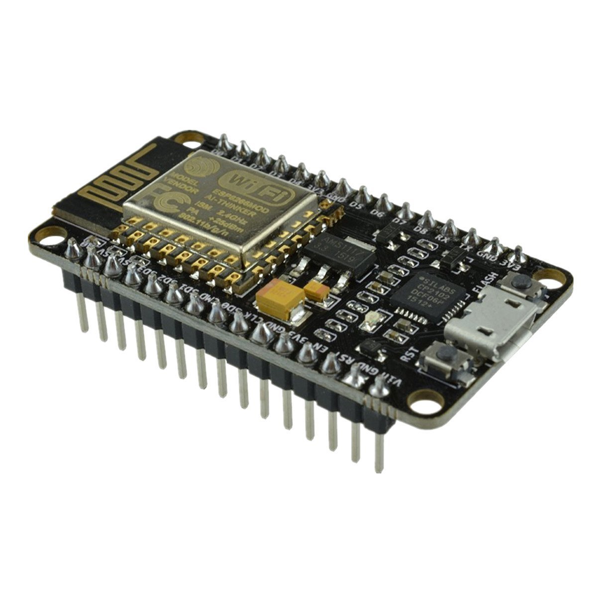
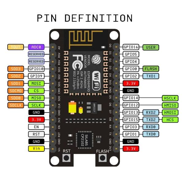
NodeMCU
QuickStart
https://benlo.com/esp8266/esp8266QuickStart.html
http://theelectromania.blogspot.de/2016/02/how-to-program-esp8266-esp-12e-nodemcu.html
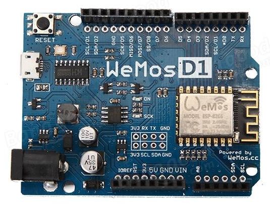
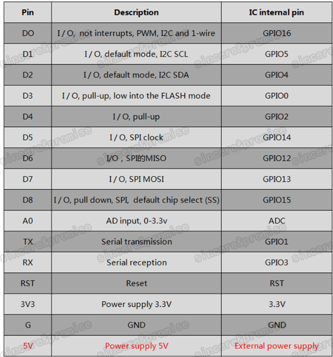
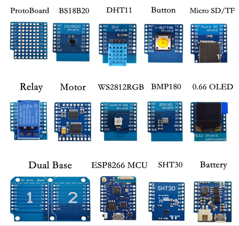
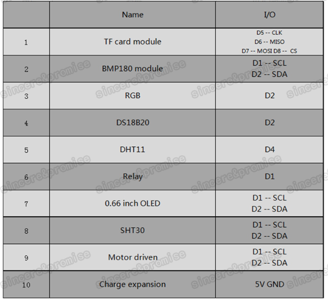
Wemos D1
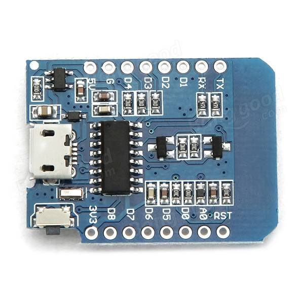
Wemos D1 Mini
Boards
D1 Mini Pro
Battery Board
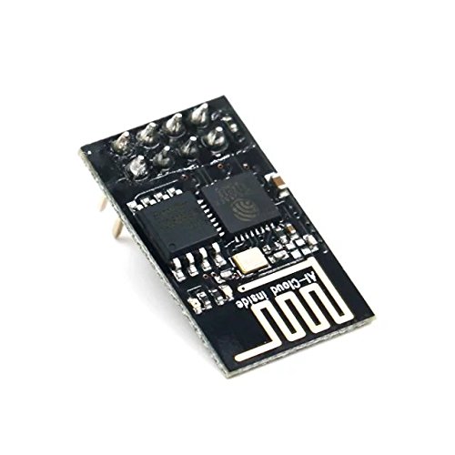
ESP 01
ESP 07
ESP 12
GP2Y10
https://www.letscontrolit.com/wiki/index.php/GP2Y10
ESP Easy Sensoren in FHEM einbinden
https://waschto.eu/easyesp-sensoren-in-fhem-einbinden
Tinkerblog : ESP2866 & ESPEasy
https://tinkerblog.net/wemos-d1-mini-node-mcu-esp-easy/
ESPEASY PN532
https://www.letscontrolit.com/wiki/index.php/PN532
Statusdisplay mit ESP Easy, DLCD und FHEM
https://waschto.eu/statusdisplay-mit-esp-easy-dlcd-und-fhem/
Fhem: LCD 2004 Display mit ESPEasy als Statusanzeige
https://blog.moneybag.de/fhem-lcd-2004-display-mit-espeasy-als-statusanzeige/
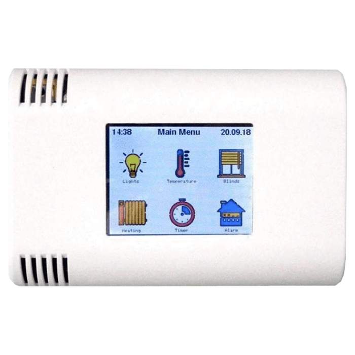
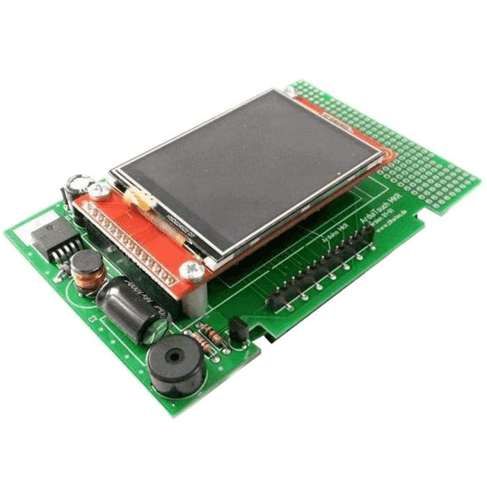
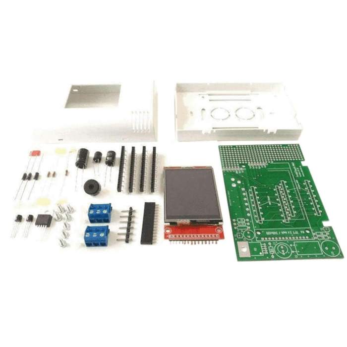
ArduiTouch Wandgehäuse Set für ESP8266 und ESP32
Wandgehäuse 120mm x 80mm x 35mm (W x H x D). 2,4 Zoll (6,14cm) Farb-TFT mit 320 x 240 Pixeln (ILI9341). Resistiver Touchscreen (Touchcontroller XPT2046)
Integrierter 5V Spannungsregler (Eingangsspannung 9 - 35V DC). Eingebauter Piezosummer.
https://www.az-delivery.de/blogs/azdelivery-blog-fur-arduino-und-raspberry-pi/arduitouch-wandgehaeuseset-mit-touchscreen-fuer-esp32-und-esp8266
https://www.hwhardsoft.de/english/projects/arduitouch-esp/
NodeMCU und ESP8266 – Einstieg in die Programmierung
https://www.mikrocontroller-elektronik.de/nodemcu-esp8266-tutorial-wlan-board-arduino-ide/
ESP Typen
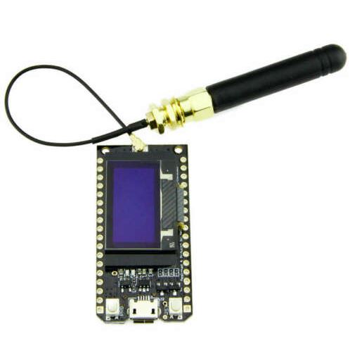
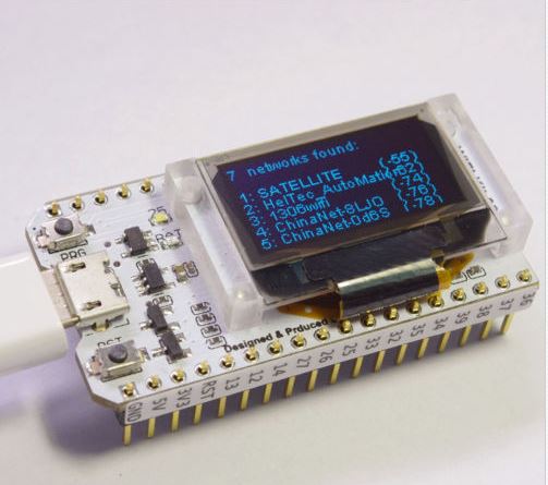
Bluetooth Wifi ESP-32 Entwicklungs Board Modul Lora32 Lora 868Mhz Esp32 Lor M5J7
Hauptmerkmale:
SX1276-Chip basierend auf ESP32-WLAN, 868 - 915 MHz-Frequenz, hohe Empfindlichkeit über -148 dBm, + 20 dBm Ausgangsleistung, hohe Zuverl? ssigkeit, lange übertragungsdistanz
Integrierte 32 MB Flash-Wi-Fi-Antenne, 0,96-Zoll-Blau-OLED-Display, Lithium-Batterie-Ladeschaltung, CP2102-Schnittstelle und serieller USB-Chip, perfekte Unterstützung für die Arduino-Entwicklungsumgebung, kann für die Programmprüfung verwendet werden, die Produktentwicklung ist sehr einfach und schnell
Spezifikationen:
Betriebsspannung: 3,3 - 7 V
Betriebstemperaturbereich: -40 bis 90 ℃ (-40 bis 194 ° F)
Unterstützung für Sniffer-Softwareprotokollanalyse-, Stations-, SoftAP- und Wi-Fi Direct-Modi
Datenraten: 150 Mbps bei 11n HT40, 72 Mbps bei 11n HT20, 54 Mbps bei 11 g, 11 Mbps bei 11b
Sendeleistung: 19,5 dBm bei 11b, 16,5 dBm bei 11 g, 15,5 dBm bei 11n
Empf?ngerempfindlichkeit bis -98 dBm
Durchgehender UDP-Durchsatz: 135 Mbps
Farbe: schwarz
Material: Metall + PC
Lieferumfang: 1 * Bluetooth WIFI ESP-32 Entwicklungsboard-Modul
Erinnerungen:
1) Die 868/915 MHz Antenne muss mit der IPEX-Schnittstelle verbunden sein (wenn die Antenne nicht angeschlossen ist, kann dies den LoRa-Chip besch?digen)
2) Wenn der Akku voll ist, funktioniert die blaue LED nicht mehr.
3) Achten Sie bei der Verwendung auf das Plus und Minus der Batterie, da diese sonst bescädigt wird.
4) Beim Touchscreen-Eingangssignal des IO-Ports müssen Sie den 100nF-Pull-Down-Kondensator zu diesem Pin hinzufügen.
ESP32 WIFI chip 0.96 inch OLED Bluetooth WIFI Kit CP2102 32M module for arduino
WIFI Kit 8 is developed by our company cost-effective Internet of things development program, the main chip using ESP8266, with CP2014USB to serial chip, lithium battery interface and charge and discharge circuit, 32MByte Flash, WIFI antenna, 0.91-inch OLED display.
Can be programmed in Ard uino and NodeMCU environments. Operation is consistent with NodeMCU.
Leads all pins of ESP8266
12 digital pins can be configured to read, write, IIC, SPI, the middle, PWM and other functions
1 AD input
Integrated 0.91-inch 128 * 32 OLED
Working voltage: 3.3V ~ 7V
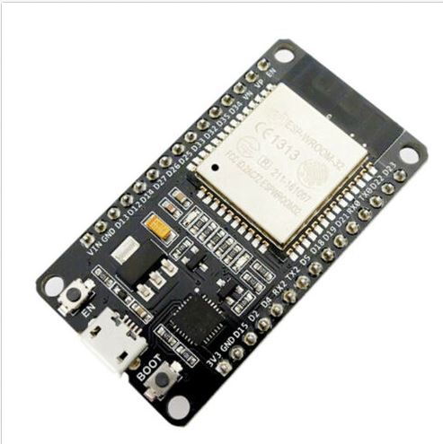
ESP-32 Entwicklungsboard WiFi Bluetooth 2 in 1 Dual Core 2,4 GHz Antennenmodul
Eigenschaften:
100% nagelneu und hohe Qualität !
Typ: ESP32 Entwicklungsboard
Hohes Preis-Leistungs-Verhältnis
Kleines Volumen, leicht in andere Produkte eingebettet
Starke Funktion mit Unterstützung LWIP-Protokoll, Freertos
Unterstützen Sie 3 Modi: AP, STA und AP + STA
Unterstützung Lua-Programm, leicht zu entwickeln
Einführung:
ESP32 ist bereits integrierte Antenne und HF-Balun, Leistungsverstärker, rauscharme Verstärker, Filter,
und Energiemanagement-Modul. Die gesamte Lösung nimmt den geringsten Platz auf der Leiterplatte ein.
Dieses Board wird mit 2,4 GHz Dual-Mode-Wi-Fi und Bluetooth-Chips von TSMC 40nm Low-Power-Technologie verwendet,
Leistung und HF-Eigenschaften am besten, die sicher, zuverlässig und skalierbar für eine Vielzahl von Anwendungen ist.
ESP32-Cam
https://www.letscontrolit.com/forum/viewtopic.php?t=6710
https://hackspace.raspberrypi.org/articles/esp32-cam-review
https://community.home-assistant.io/t/esp32-cam-working/109140/22

https://randomnerdtutorials.com/esp32-cam-video-streaming-face-recognition-arduino-ide/
https://www.mikrocontroller.net/topic/esp32-cam-entwicklungskit
https://randomnerdtutorials.com/esp32-cam-take-photo-display-web-server/
https://www.fambach.net/esp32-cam-modul/
https://www.hackster.io/news/using-a-camera-with-the-esp32-9d6994b34a2b
https://www.youtube.com/watch?v=5XCb3t8J4Kg
https://www.youtube.com/watch?v=q7Z_XnBYFhY
http://iot-bits.com/esp32/esp32-flash-download-tool-tutorial/
http://iot-bits.com/esp32/getting-started-with-esp32-esp-idf-part-1/
https://www.fambach.net/ispy/
DSTIKE
DSTIKE Bad Watch
https://dstike.com/products/dstike-bad-watch
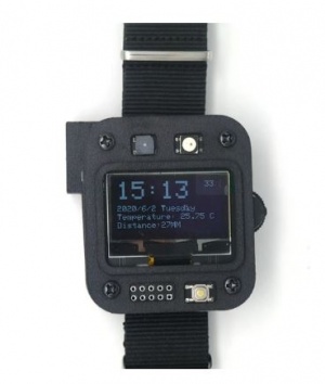
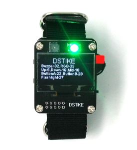
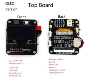
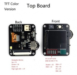
DSTIKE ESP32 Watch DevKit (Two versions)
https://dstike.com/products/dstike-esp32-watch-devkit
What makes it special?
Small size: 3.8x4.5cm
Height:1.5cm
Double 4 layer board
600mAh battery inside
On/OFF Power Switch
OLED version:1.3OLED SH1106(SDA-17,SCL-16)
TFT color version: ST7789 240*240 LCD(SDA-17,SCL-16,DC-22,RES-23)
Buzzer-32
WS2812b RGB LED-33
Navigation Button(Up-19,Center-18,Down-5)
OLED version external slide button(22,23)
Highlight LED(27)
Indicate charging LED(On means Charging,OFF means Full)
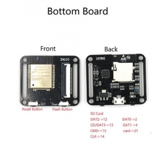
Reset and Flash Button at Bottom board
Breakout GPIOs(TX,RX,17,16,SVP,SVN,25,26,GND,3V)
SD Card support
GPIO12--DAT2
GPIO13--DAT3
GPIO15--CMD
GPIO14--CLK
GPIO2--DAT0
GPIO4--DAT1
GPIO21--card
Code
https://github.com/lspoplove/D-duino-project/blob/master/ESP32WatchDev/ESP32WatchTest.ino
https://github.com/ThingPulse/esp8266-oled-ssd1306
https://github.com/lspoplove/Arduino-ST7789-Library
https://github.com/adafruit/Adafruit_NeoPixel
Init
#include <Adafruit_NeoPixel.h>
#include "SH1106.h"
#define BUTTON_PRESS   18
#define BUTTON_LEFT    5
#define BUTTON_RIGHT   19
#define PIXEL_PIN    33    // Digital IO pin connected to the NeoPixels.
#define PIXEL_COUNT 1
#define BUZZER 32
#define BUTTON_ON 22
#define BUTTON_OFF 23
#define FLASHLIGHT 27
SH1106  display(0x3c,17,16);
Adafruit_NeoPixel strip = Adafruit_NeoPixel(PIXEL_COUNT, PIXEL_PIN, NEO_GRB + NEO_KHZ800);
RGB LED
#include "Freenove_WS2812_Lib_for_ESP32.h"
#define LEDS_COUNT  1
#define LEDS_PIN	33
#define CHANNEL		0
Freenove_ESP32_WS2812 strip = Freenove_ESP32_WS2812(LEDS_COUNT, LEDS_PIN, CHANNEL, TYPE_GRB);
u8 m_color[5][3] = { {255, 0, 0}, {0, 255, 0}, {0, 0, 255}, {255, 255, 255}, {0, 0, 0} };
int delayval = 100;
void setup() {
Strip.begin();
strip.setBrightness(10);
}
void loop() {
for (int j = 0; j < 5; j++) {
for (int i = 0; i < LEDS_COUNT; i++) {
strip.setLedColorData(i, m_color[j][0], m_color[j][1], m_color[j][2]);
strip.show();
delay(delayval);
}
delay(500); } }
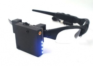
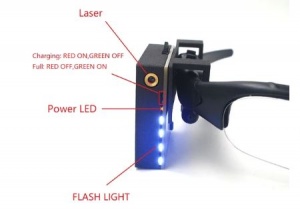
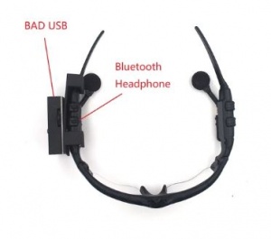
DSTIKE BAD GLASS
https://dstike.com/products/dstike-bad-glass
