Elektronik
Willkommen auf unserer Elektronik Wiki Seite
Inhaltsverzeichnis
- 1 Shops
- 2 Schaltzeichen
- 3 DDR Bausätze
- 4 Simulator
- 5 Webseiten
- 6 Bauteile Passiv
- 7 Das Elektronik-Labor
- 8 Fritzing
- 9 EleLa - Elektronik Lagerverwaltung ab V2.0
- 10 Sunfounder
- 11 sms-guard
- 12 CAN Bus
- 12.1 CANned Pi: (Part1)
- 12.2 RS485 CAN HAT for Raspberry Pi
- 12.3 MCP2515 CAN Bus Modul - TJA1050 Transceiver 5V Arduino Raspberry Pi
- 12.4 NEU SN65HVD230 CAN bus transceiver communication module For Arduino de
- 12.5 SN65HVD230 CAN Board Network Transceiver Evaluation Development Module
- 12.6 High Speed Bus Interface Protocol Controller MCP2551 Can Communication Module
- 12.7 USB-CAN USB to CAN BUS Converter Adapter + USB Cable support win7 System
- 12.8 OBD 2
- 13 RFID
- 14 USB
- 15 Messgeräte
- 15.1 Funktionsgenerator IC-XR2206 als Bausatz
- 15.2 FR4+Acryl Signal Generator DIY-Kit LCD-Anzeige Vorwärtswelle Funktion Praktisch
- 15.3 PWM Board Module Pulse Frequency Duty Cycle Adjustable Module LCD Display
- 15.4 DIY Kits NE555 Multi-Channel Waveform Generator Suite For Electronic Experiment
- 15.5 DSO 138Mini Osziloscope Bausatz
- 15.6 Bauteil Tester GM328
- 16 SMD
- 17 Löten
- 18 Bauteile
- 18.1 Wiring.org Tutorial
- 18.2 Slide Potentiometer 10K Linear Module Dual Output
- 18.3 Rotary Encoder EC12 Audio Digital Potentiometer 15mm Handle
- 18.4 Gabellichtschranke
- 18.5 LED
- 18.6 Displays
- 18.7 Pegelwandler
- 18.8 Infrarot Empfänger
- 18.9 SPI
- 18.10 I2C
- 18.10.1 PCF 8566
- 18.10.2 PCF 8570
- 18.10.3 PCF 8573
- 18.10.4 PCF 8574 P I2C Port Expander
- 18.10.5 PCF8575 IO Expander Tafel Modul I2C Bis 16 IO Zum Arduino Module GE
- 18.10.6 PCF 8582
- 18.10.7 PCF 8584 I2C-bus Controller
- 18.10.8 PCF 8591
- 18.10.9 YL-40 PCF8591 8 Bit Analog-Digital-Wandler ADC I2 C YL-40 Arduino
- 18.10.10 DS 1620
- 18.10.11 EEProms 24C02
- 18.10.12 PN532 NFC RFID
- 18.10.13 OLED Display
- 18.10.14 TM1638 LED&Key
- 18.10.15 DS3231
- 18.10.16 DS3231 Real Time Clock Module für arduino 3,3 V/5 V mit batterie Für Raspberry Pi
- 18.10.17 SRF 08 Ultraschall Abstandssensor
- 18.10.18 HC-SR04 Ultraschall Abstandssensor
- 18.10.19 MCP23017 I2C interface 16bit I/O Extension Module Pin Board IIC to GIPO Convert
- 18.10.20 BMP180 Barometer
- 18.10.21 BMP280 GY-BME280 Barometrischer Sensor für Temperatur, Luftfeuchtigkeit und Luftdruck
- 18.10.22 SHT30-D
- 18.10.23 SHT31-D
- 18.10.24 Diymore I2C IIC INA226 Spannung Strom Power Monitor Modul Überwachung Alarm Alarm Funktion Bord Interface 36V Bi-Directional
- 18.10.25 Full Color RGB LED Strip Driver Module Shield for Arduino STM32 AVR
- 18.10.26 INA3221 3 Channel Shunt Current Voltage Monitor Sensor Replace INA219 Module w
- 18.11 ICs
- 19 Module
- 19.1 MINI L293D Arduino Motorantrieb Erweiterungskarte Mini L293D Motorantrieb Modul Deek Robot Motor Shield V1
- 19.2 3 in 1 Remote Control + HX1838 Receiver + Coded Infrared Module with Female to Female Dupond Line Wire Cable Free Shipping
- 19.3 HC-SR501 Body Sensor Module Adjust IR PIR Pyroelectric Infrared PIR Motion Human Sensor Detector Module For Arduino
- 19.4 BV4221
- 19.5 RS232-TTL
- 19.6 HC-05
- 19.7 BlueSmirf
- 19.8 RFM12
- 19.9 Tastenfeld
- 19.9.1 Arduino Keypad Pinout
- 19.9.2 3x4
- 19.9.3 TTP224 4 Schlüssel Buttons Touch-Switch-Modul Touch-Kapazität Digital-Wandler Vorstand Sensor 2,4V-5,5V
- 19.9.4 TTP226 8-Kanal-kapazitiver Schalter Digital Touch Sensor Board-Modul für Arduino
- 19.9.5 TTP229 16-Channel Digitaler Touch Kapazitiver Sensor Modul XD-62B TTP229
- 19.9.6 4x4
- 19.9.7 Folientastatur mit i2C Portexpander PCF8574
- 19.9.8 ESP Easy Tastatur und PCF8574
- 19.9.9 I2C
- 19.10 SD Card
- 19.11 Mini Datenlogger Modul Protokollierung Schild für Arduino Für Raspberry Pi Protokollierung Recorder Datenlogger Modul Schild V1.0 SD Karte
- 19.12 PC817 Optokoppler
- 20 Sensoren
- 20.1 50 DER WICHTIGSTEN RASPBERRY PI SENSOREN UND MODULE
- 20.2 Infrared Reflective Photoelectric Switch TCRT5000 Ir Barrier Line Track Senso io
- 20.3 YL-40 PCF8591 8 Bit Analog-Digital-Wandler ADC I2 C YL-40 Arduino
- 20.4 Luftqualität
- 20.5 3 Achsen Beschleunigung MEMS1
- 20.6 GY-521 3 Achsen MPU-6050 Beschleunigungssensor / Gyroskop / Accelerometer
- 20.7 X9C103S Digital Potentiometer Board Module DC3V-5V for Arduino 10K Span Potentiometer
- 20.8 Kompassmodul HDMM01
- 20.9 Flexsensor 2.2
- 20.10 37-IN-1-SENSOR-KITS-FOR-ARDUINO
- 20.10.1 sensorkit.joy-it.net
- 20.10.2 Arduino
- 20.10.3 RaspBerryPi
- 20.10.4 KY-001 DS18B20
- 20.10.5 KY-002
- 20.10.6 KY-003 HALL MAGNETIC SENSOR MODULE
- 20.10.7 KY-004 Button
- 20.10.8 KY-005
- 20.10.9 KY-006 Buzzer
- 20.10.10 YL-44
- 20.10.11 KY-007
- 20.10.12 KY-008 Laser
- 20.10.13 KY-009 3C LED
- 20.10.14 KY-010
- 20.10.15 KY-011
- 20.10.16 KY-012
- 20.10.17 KY-013
- 20.10.18 KY-014
- 20.10.19 KY-015 Temp/Hum
- 20.10.20 KY-016
- 20.10.21 KY-017
- 20.10.22 KY-018 FotoR
- 20.10.23 KY-019 Relay
- 20.10.24 KY-020
- 20.10.25 KY-021
- 20.10.26 KY-022
- 20.10.27 KY-023
- 20.10.28 KY-024 Linear magnetic Hall Sensor
- 20.10.29 KY-025
- 20.10.30 KY-026
- 20.10.31 KY-027
- 20.10.32 KY-028
- 20.10.33 KY-029
- 20.10.34 KY-030
- 20.10.35 KY-031
- 20.10.36 KY-032
- 20.10.37 KY-033
- 20.10.38 KY-034
- 20.10.39 KY-035 magnetischer Hall Sensor Modul
- 20.10.40 KY-036
- 20.10.41 KY-037
- 20.10.42 KY-038
- 20.10.43 KY-039
- 20.10.44 KY-040 Rotary Encoder
- 20.10.45 WIKI
- 20.11 Gas Sensoren MQ
- 20.12 Pulsesensor
- 20.13 Sensormodul Regen Wetter Modul
- 20.14 Feuchtigkeitssensor
- 20.15 SHARP IR Ranger Sensor GP2D12
- 20.16 Fingerprint Sensor
- 20.17 GY-471 MAX471 3A Palette Aktuelle Sensor Modul Professionelle MAX471 Modul Für Arduino
- 20.18 RCWL-0516
- 21 Spannungsversorgungen
- 21.1 Spannunmgsregler
- 21.2 DC 5-24V to Dual Power ±12V ±5V +3.3V Boost USB Linear Regulator Module DIY Kit
- 21.3 Spannungsversorgung 5V/3,3V
- 21.3.1 Power
- 21.3.2 MB102
- 21.3.3 3,3 V 5V 12V Multi Ausgang Spannung Umwandlung DC-DC 12V zu 3,3 V 5V 12V power Module
- 21.3.4 TSP 03
- 21.3.5 TSP 05
- 21.3.6 5V 700mA 3.5W
- 21.3.7 2PCS Ultra-small LM2596 power supply module DC / DC BUCK 3A adjustable buck module regulator ultra LM2596S 24V switch 12V 5V 3V
- 21.3.8 LM2596S Step-down DC-DC Buck Converter mit 3-stelliger Digitalanzeige
- 21.3.9 Mini Buck Step Down Converter DC-DC 1.2V 2.5V 3V 3.3V 5V Power Supply Module
- 21.3.10 XL6009 DC-DC einstellbarer Step-UP Spannungsregler Power Boost Modul
- 21.3.11 AC 220V 230V to DC 3.3V 5V 9V 12V Step Down Converter Board Power Supply Module
- 21.3.12 Mini DC-DC 12-24V Zu 5V 3A Step Down Netzteil Modul Spannung Buck Converter einstellbar 97.5% 1,8 V 2,5 V 3,3 V 5V 9V 12V
Shops
https://eckstein-shop.de/
https://www.ramser-elektro.at/shop/
https://www.muekra.de/
https://www.funduinoshop.com/
Schaltzeichen
https://de.wikipedia.org/wiki/Liste_der_Schaltzeichen_(Elektrik/Elektronik)#Widerst%C3%A4nde
https://en.wikipedia.org/wiki/Electronic_symbol
DDR Bausätze
http://www.blunk-electronic.de/BB/
Simulator
https://www.falstad.com/circuit/circuitjs.html
== Elektronik-Kompendium ==
https://www.elektronik-kompendium.de/
Webseiten
USB Wikipedia
https://de.wikipedia.org/wiki/Universal_Serial_Bus#USB_3.0
Afug Info
http://www.afug-info.de
Bauteile Passiv
Widerstand
https://www.digikey.de/de/resources/conversion-calculators/conversion-calculator-resistor-color-code
http://www.calculino.com/de/elektronik/ohmscher-widerstand_rechner.html
Kondensator
Kennzeichnung Kondensatoren
https://www.elektronik-kompendium.de/sites/bau/1109061.htm
http://www.jukebox-world.de/Forum/Archiv/FAQ-Technik/Kondensator.htm
Kondensator mit Arduino Nano messen
http://shelvin.de/kondensator-messen-mit-dem-arduino-theorie-aufbau-und-das-programm/
http://shelvin.de/kapazitaeten-von-10nf-bis-2000uf-einfach-messen-mit-dem-arduino/
http://shelvin.de/kapazitaeten-von-1uf-2000uf-einfach-messen-mit-dem-arduino/
https://elektro.turanis.de/html/prj080/index.html
https://www.az-delivery.de/blogs/azdelivery-blog-fur-arduino-und-raspberry-pi/prototyp-eines-kapazitatsmessgerates?utm_source=AZ-MAILING+DEUTSCH&utm_campaign=eea44b6fc8-EMAIL_CAMPAIGN_7_31_2021_Blog_COPY_01&utm_medium=email&utm_term=0_569b1a8f94-eea44b6fc8-18682151&goal=0_569b1a8f94-eea44b6fc8-18682151&mc_cid=eea44b6fc8&mc_eid=12f0ec326f
Relais
SANYOU SRB-S-112 DM 12VDC SRB-S-112DM 5A 277VAC 30VDC Relay 4Pins
SANYOU SYS-S-112L SYS-S-112L New Sanyou Sealed type 1 pole 12V L Relay 1A 125VAC / 1A 30VDC
TE TSC-112-L3H (12V) TSC-112L3H.000 TE Connectivity General Purpose Relays SPDT 1A 12DC STD SNS /uk
Matsushita JSM1a-9V-5 Matsushita Leistungsrelais 9V Dc 5A JSM1A-9V-5 Spst-No
Zettler AZ6961-1A-5D Power Relay 5VDC 10A SPST-NO(28.75x10.35x12.55)mm THT
Meder SIL05-1A72-71D SIL051-A7271D SIL-Reed-Relais 5V= 1xEIN 500 Ohm mit Diode parallel MEDER SIA05D https://cdn-reichelt.de/documents/datenblatt/C300/DATASHEET_REED_RELAY_SIL.pdf
Quarz
Oszilator


http://mschrod.de/elektronetz/Elektronik/Datenblaetter/Quarzoszillator.pdf
BreadBoard
25 Polig

55 Polig

Das Elektronik-Labor
Fritzing
EleLa - Elektronik Lagerverwaltung ab V2.0
Sunfounder
sms-guard
CAN Bus
https://de.wikipedia.org/wiki/Controller_Area_Network
https://en.wikipedia.org/wiki/CAN_bus
https://wiki.ta.co.at/CAN-Bus
CANned Pi: (Part1)

http://skpang.co.uk/catalog/pican2-canbus-board-for-raspberry-pi-2-p-1475.html
https://www.cowfishstudios.com/blog/canned-pi-part1
https://www.hackster.io/youness/how-to-connect-raspberry-pi-to-can-bus-b60235
https://crycode.de/can-bus-am-raspberry-pi
https://www.beyondlogic.org/adding-can-controller-area-network-to-the-raspberry-pi/
RS485 CAN HAT for Raspberry Pi

https://www.waveshare.com/rs485-can-hat.htm
https://www.waveshare.com/wiki/RS485_CAN_HAT
WaveShare RS485 CAN HAT for Raspberry Pi
RS485 CAN HAT für Raspberry Pi, ermöglicht stabile Kommunikation über lange Distanzen
Überblick
Mit dem RS485 CAN HAT kann Ihr Pi über RS485/CAN-Funktionen stabil mit anderen Geräten über große Entfernungen kommunizieren.
Merkmale
Standard Raspberry Pi 40PIN GPIO-Erweiterungsheader, unterstützt Boards der Serie Raspberry Pi
CAN-Funktion, Onboard-CAN-Controller MCP2515 über SPI-Schnittstelle, Onboard-Transceiver SN65HVD230
RS485-Funktion, gesteuert über UART, Halbduplex-Kommunikation, unterstützt automatische TX/RX-Steuerung ohne Programmierung, Onboard- Transceiver SP3485
Onboard TVS (Transient Voltage Suppressor), unterdrückt effektiv Überspannung und transiente Spannungsspitzen in der Schaltung für RS485
Transceiver, blitzschutz & antielektrostatisch Reservierte Steuerpins, erlaubt die Arbeit mit anderen Steuerplatinen
Kommt mit Entwicklungsressourcen und Handbuch (Beispiele in wiringPi/python)

Spezifikationen
Betriebsspannung: 3,3V
CAN-Steuerung: MCP2515
CAN-Sender/Empfänger: SN65HVD230
485 Sender-Empfänger: SP3485
Abmessung: 65mm x 30mm
Befestigungslochgröße: 3,0 mm
Empfohlen
Wir bieten auch einen isolierten Schnittstellenwandler USB TO RS232/485/TTL zum einfachen Testen an.
Lieferumfang
RS485 KANN HAT x1
RPi-Schraubenpackung(2Stk.) x1
CanBus mit dem Raspberry Pi
https://forum-raspberrypi.de/forum/thread/13161-canbus-mit-dem-raspberry-pi/
sudo /sbin/ip link set can0 up type can bitrate 500000
ifconfig
wget http://www.skpang.co.uk/dl/can-test_pi2.zip &&  unzip can-test_pi2.zip
cd can-test_pi2/ && sudo candump can0
https://www.skpang.co.uk/pages/install
https://wiki.rdu.im/_pages/Application-Notes/Hardware/Embedded-Boards/Raspberry-Pi.html
https://www.skpang.co.uk/pages/installing-python-can-for-raspberry-pi
https://github.com/skpang/PiCAN-Python-examples
https://gist.github.com/InfinityCliff/c9621bf8ed8b1ecd6112b4e82e108fc4
MCP2515 CAN Bus Modul - TJA1050 Transceiver 5V Arduino Raspberry Pi

Vollfertiges CAN-Bus Modul zum Betrieb z.B. an Arduino oder Rapsberry Pi per SPI Schnittstelle.

Technische Daten:
Betriebsspannung: 5V
Logikspannung: 5V
Chip: MCP2515|TJA1050
SPI – 10MHz
CAN 2.0B
NEU SN65HVD230 CAN bus transceiver communication module For Arduino de

nd high quality!
SN65HVD230 can be used under high interference environment.
The device has the ability to send and receive good at different rates,
Fully compatible with ISO11898 standard;
High input impedance, allowing 120 nodes;
Low current standby mode, the typical current of 370μA;
Signal transfer rate up to 1Mb / s;
Thermal protection, open circuit failure protection function;
With anti-instantaneous interference protection bus;
Slope control, reduce radio frequency interference (RFI);
Differential receiver with a wide range of anti-common-mode interference,
electromagnetic interference (EMI) capabilities.
Specifications:
Operates With a 3.3V Supply
Color: Blue
SN65HVD230 CAN Board Network Transceiver Evaluation Development Module

The SN65HVD230 CAN Board is an accessory board features an onboard CAN transceiver SN65HVD230, which is pinout compatible with PCA82C250. It is powered from 3.3V and features ESD protection.
The SN65HVD230 CAN Board is ideal for connecting microcontrollers to the CAN network.
Specifications:
Material:PCB
Color:Blue
Size:38x11x10mm/1.49x0.43x0.39 Inch
Weight:3g
High Speed Bus Interface Protocol Controller MCP2551 Can Communication Module

MCP2551 is a fault-tolerant, high-speed CAN devices can be used as CAN protocol controller and the physical bus interface. MCP2551 provides differential receive capability to the CAN Protocol controller, which is fully in line with ISO-11898 standards, including energy 24V requirements.
Typically, each node on the CAN system must have a device, the digital signal is converted into CAN controller generates a signal for bus transport. It also provides high voltage spikes between CAN controller and CAN bus joined the buffer, these high-pressure spikes may be generated by an external device.
Support 1MB / S's run rate.
Meet the ISO-11898 standard physical layer requirements.
Suitable for 12V and 24V systems. Slope external control, reduce RFI.
Automatic detection TXD input ground fault.
Power-on reset and voltage brown-out protection.
Unpowered node or Brown will not affect CAN bus.
Low current standby operation.
Up to 112 nodes can be connected
USB-CAN USB to CAN BUS Converter Adapter + USB Cable support win7 System

This product is lower machine using 32-bit high-performance ARM chip development, PC software development based on previous experience of site commissioning CAN communication, as much as possible to achieve a powerful, easy to use, clear, no description can be used directly, the perfect software support win7 system, including 64-bit win7, CAN communication support maximum baud rate of 1M;

compared with other CAN software, in addition to the perfect support for CAN standard frame (2.0A) and extended frame (2.0B) send and receive data, set the filtering will Standby function, also increased the saved communication data records (text and EXCEL in two ways), in addition to sending and receiving data to increase the visual custom baud rate, auto-answer response data, millisecond data, while increasing the multi-frame data transmission options can be edited directly online data, etc., to make debugging easier.
OBD 2
https://en.wikipedia.org/wiki/OBD-II_PIDs
https://www.youtube.com/watch?v=cAAzXM5vsi0
RFID
RFID-RC522

RFID RC522 module, S50 card (13.56MHz), S50 key fob (13.56MHz), pin headers
Produktbeschreibungen
Beschreibung:
* MFRC-522 RC522 RFID Modul IC-Karte induktiver Sensor mit S50-Karte keychain.
* Dieses Modul kann direkt in die verschiedenen Leserformen geladen werden.
* Dieses RFID-Lesermodul kann in einer breiten Vielfalt eingesetzt werden, einschließlich Zutrittskontrolle, automatische Identifikation, Robotik, Inventarverfolgung, Zahlungssysteme etc.
* Unterstützte Kartentypen: mifare1 S50, mifare1 S70 MIFARE Ultralight, mifare Pro, MIFARE DESFire
Spezifikation:
* Modell Nr .: RFID-RC522
* Leerlaufstrom: 10-13mA / DC 3.3V
* Schlafstrom: <80uA
* Spitzenstrom: <30mA
* Betriebsfrequenz: 13.56MHz
* Betriebsstrom: 13-26mA, DC 3.3V
* Betriebstemperatur: -20 bis 80 Grad
* Lagertemperatur: -40 bis 85 Grad
* Modul Szie: 4 x 6 cm
* Modul Gewicht: 9gram
* Karte Szie: 5.4 x 8.6cm
* Karte Gewicht: 6 Gramm

Willkommen auf der RFID Wiki Seite
http://air.imag.fr/index.php/RFID-RC522_RF_IC_Card_Sensor_Module_203517
https://www.alldatasheet.com/datasheet-pdf/pdf/227839/NXP/MFRC522.html
https://html.alldatasheet.com/html-pdf/227839/NXP/MFRC522/54/1/MFRC522.html
RaspberryPi

Webseiten
http://www.nikolaus-lueneburg.de/2014/06/rfid-rc522-modul-mit-spi-schnittstelle/
http://www.elli-blog.de/?p=41
https://github.com/mxgxw/MFRC522-python/blob/master/Read.py
http://geraintw.blogspot.de/2014/01/rfid-and-raspberry-pi.html?showComment=1422882869378#c6295757221222802715
http://tutorials-raspberrypi.de/raspberry-pi-rfid-rc522-tueroeffner-nfc/
Einrichtung
Download aktuelles Image
https://www.raspberrypi.org/downloads
Konfiguration
sudo /usr/bin/raspi-config
Hostname ändern
Internationale Einstellungen ändern
I2c aktivieren
SPI aktivieren
Installieren XRDP
sudp apt-get install xrdp
I2C / SPI
sudo nano /etc/modules
i2c-dev
i2c-bcm2708
spi-bcm2708
sudo nano /etc/modprobe.d/raspi-blacklist.conf
#blacklist spi-bcm2708
#blacklist i2c-bcm2708
blacklist snd-soc-pcm512x
blacklist snd-soc-wm8804
Device Tree
Eleganter ist es, einen schnittstellenspezifischen Parameter in der Datei /boot/config.txt einzutragen. Normlalerweise sind die Schnittstellen durch ein Kommentarzeichen (#) deaktiviert:
#dtparam=i2c_arm=on
#dtparam=i2s=on
#dtparam=spi=on
Modul Installation
# sudo apt-get install python-dev
# sudo apt-get install gcc
# git clone https://github.com/lthiery/SPI-Py
# cd SPI-Py
#  sudo python setup.py install
# git clone https://github.com/mxgxw/MFRC522-python
# cd MFRC522-python
# sudo python Read.py
Arduino

Pin Belegung
 SS or SDA > Pin 10
 SCK > Pin 13
 MOSI > Pin 11
 MISO > Pin 12
 IRQ
 Ground > Ground
 Reset > Pin 5
 3.3v > 3.3v
How to get started with the Mifare MF522-AN and Arduino
https://github.com/miguelbalboa/rfid
Code RFID testen
 #include <SPI.h>
 #include <MFRC522.h>
 #define SS_PIN 10
 #define RST_PIN 5
 MFRC522 mfrc522(SS_PIN, RST_PIN);
 void setup()
 {
 Serial.begin(9600);
 SPI.begin();
 mfrc522.PCD_Init();
 Serial.print("Start RFID");
 }
 void loop()
 {
 if ( ! mfrc522.PICC_IsNewCardPresent())
 {
 return;
 }
 if ( ! mfrc522.PICC_ReadCardSerial())
 {
 return;
 }
 Serial.print("Die ID des RFID-TAGS lautet:");
 for (byte i = 0; i < mfrc522.uid.size; i++)
 {
 Serial.print(mfrc522.uid.uidByte[i], HEX);
 Serial.print(" ");
 }
 Serial.println();
 }
http://playground.arduino.cc/Learning/MFRC522
http://www.instructables.com/id/Arduino-RC522-RFID-Door-Unlock/
http://www.instructables.com/id/Arduino-RFID-Reader-MFRC522-Turorial/
http://arduino-er.blogspot.de/2015/10/arduino-uno-rfid-rc522-mfrc522-library.html
http://funduino.de/index.php/3-programmieren/nr-19-rfid
http://fluuux.de/2015/08/eine-tuer-mit-rfid-chip-oeffnen-rfid-rc522/
https://www.loxforum.com/forum/faqs-tutorials-howto-s/21162-rfid-reader-arduino-ethernet-rc522
https://electricalkida.blogspot.com/2019/03/esp-32-with-rfid-mfrc522-1-you-download.html
Homematic
http://www.forum-raspberrypi.de/Thread-rfid-rc522-und-homematic
FHEM
lesen von Werten
http://192.168.0.44:8083/fhem&cmd=%7BValue%28%22RFIDTest%22%29%7D&XHR=1
Python
import urllib
sock = urllib.request.urlopen("http://diveintopython.org/")
htmlSource = sock.read()
sock.close()
print (htmlSource)
setzen von Werten
http://192.168.0.44:8083/fhem&cmd.RFIDTest=set%20RFIDTest%20 ON / OFF
http://192.168.0.44:8083/fhem&cmd.RFIDTest=set%20RFIDTest%20SN%20xx123456
Python
import urllib
urllib.urlretrieve('http://192.168.0.1:8181/x.exe?Antwort=dom.GetObject("BidCos-RF.IEQ0012345:1.STATE").State(1)')
RFID PN532 Mini Breakout Modul

http://www.nikolaus-lueneburg.de/2016/03/rfid-pn532-mini-breakout-modul/
This module is built around NXP PN532, and the maker break out almost all of the I/O pins of the NXP532 chip on this little module. This Arduino-compatible module has the following features:
Supports II2, SPI, and high-speed UART (HSU)
RFID reader/writer mode support for:
Mifare 1K, 4K, Ultralight, and DesFire cards
ISO/IEC 14443-4 cards such as CD97BX, CD light, DesFire, and P5CN072 (SMX)
Innovision Jewel cards such as the IRT5001 card
FeliCa cards such as RCS_860 and RCS_854
Built-in PCB antenna (covered by white paint)
5- to 7-cm communication distance
On-board level shifter
Standard 5-V TTL for I2C/UART and 3.3-V TTL SPI (VCC 3.3 to 5 V)
Works as an RFID reader/writer
Works as a 1443-A card or a virtual card
Supports NFC with Android phone
ESPEASY PN532
https://www.letscontrolit.com/wiki/index.php/PN532
Arduino RFID Reader mit ID-12LA
http://www.nikolaus-lueneburg.de/2015/05/arduino-rfid-reader-id-12la/
USB

Messgeräte
Funktionsgenerator IC-XR2206 als Bausatz
http://www.normei-weinheim.de/Oszillo/XR2206-Bausatz_V1.htm
http://www.ak-modul-bus.de/stat/funktionsgenerator_bausatz_xr2206_kit,pd0,,XR2206-KIT.html


FR4+Acryl Signal Generator DIY-Kit LCD-Anzeige Vorwärtswelle Funktion Praktisch


Features:
Uses ICL8038 and high-speed op amp, higher accuracy.
Can output sine/triangle/square/forward and reverse sawtooth waveforms.
LCD display to indicate the data accurately.
Frequency Range: 5Hz~400kHz; Duty Cycle Range: 2~95%(Adjustable)
Adjustable frequency and amplitude.
Supports dual power amplifier without blocking the capacitor to ensure high and low frequency signal distortion.
Frequency adjustment features coarse tuning and fine tuning.
All are through hole components, easy to install.

Specification:

Material: FR4 + Acrylic
Supply Voltage: 12V~15V
Frequency Range: 5Hz~400KHz(Adjustable)
Duty Cycle Range: 2~95%(Adjustable)
Low Distortion Sine Wave: 1%
Low Temperature Drift: 50ppm / °C
Output Triangular Wave Linearity: 0.1%
DC Bias Range: -7.5V~7.5V
Output Amplitude Range: 0.1V~11VPP(operating voltage 12V)
Board Dimension: 7.8*5cm/3.07*1.97 inch (Approx)
Finished Product Dimension: 8.7*6*1.7cm/3.43*2.36*0.67 inch (Approx)
PWM Board Module Pulse Frequency Duty Cycle Adjustable Module LCD Display

2-way 5-30v
Highlights:
Two independent PWM generators can set the frequency, duty cycle;
The wide frequency range, high accuracy;
Can serial communication.

First, the module description:
Frequency is divided into three ranges:
XXX (no decimal point): the smallest unit is 1Hz, the range 1Hz ~ 999Hz;
XX.X (decimal point in ten): The minimum unit is 0.1Khz; the range of 0.1KHz ~ 99.9KHz
X.X.X. (there are three decimal point): the smallest unit is 1Khz; the range 1KHz ~ 150KHz
Frequency display example:
""100"" indicates that the PWM output pulse of 100Hz;
""54.1"" indicates that the PWM output pulse of 54.1KHz;
""1.2.4."" Indicates that the PWM pulse output 124KHz
Duty Cycle in the range: 0 to 100;
Three frequencies duty cycle is the same, all the parameters non-volatile.

Second, the module parameters:
Working voltage: 5--30V, support micro USB 5.0V power supply;
Frequency range: 1Hz ~ 150KHz;
The frequency accuracy: ± 2%;
Output Current: Output amplitude: Default 5Vp-p (settable);
Operating temperature range: -30 ~ + 70 ℃.

Third, the parameter settings:
Module has three buttons [Set], [Up], [Down];
Press [Set] key to switch the display four parameters (FR1: PWM1 frequency; dU1: PWM1 duty cycle; FR2: frequency of PWM2; dU2: PWM2 duty cycle), before the handover parameters, there will be corresponding parameter name flash.
Press [Up], [Down] keys to modify the current parameter value (long press can quickly add or subtract fast).
Two PWM each have three preset frequency, the frequency display interface, long press [SET] key to switch between three types of frequencies, three kinds of frequency duty cycle is the same value. (XXX: range 1Hz ~ 999Hz; XX.X: range 0.1Khz ~ 99.9Khz; X.X.X .: range 1Khz ~ 150Khz,).

Fourth, the scope:
As square wave signal generator which generates a square wave signal;
to provide a signal to the stepping motor driver;
Adjustable pulse generation for chip use;
produce variable pulse signal, the control-related circuit (PWM dimming, speed).

Fifth, the serial Control
Baud rate: 9600 bps
Data bits: 8
Stop bits: 1
Parity bit: None
Flow control: none
1, set the PWM frequency
""S1FXXXT"": setting PWM1 frequency of XXX HZ (001 ~ 999)
""S1FXX.XT"": set the frequency of PWM1 XX.X KHZ (00.1 ~ 99.9)
""S1F: X.X.X.T"": setting PWM1 frequency of XXX KHZ (0.0.1 ~ 1.5.0..)
'S1': PWM1
'S2': PWM2
'F': Frequency
'D': Duty Cycle
'T' is the end flag
Set the PWM duty cycle
""S1DXXXT"": setting PWM1 duty cycle XXX; (001 ~ 100)
""S2DXXXT"": set PWM2 duty cycle XXX; (001 ~ 100)
Setting successful return: DOWN;
Setting failback: FALL.
NO Retail Box. Packed Safely in Bubble Bag.
Package Included:
1 x 2 way Independent PWM Generator"
DIY Kits NE555 Multi-Channel Waveform Generator Suite For Electronic Experiment

DSO 138Mini Osziloscope Bausatz
https://jyetech.com/forum/viewforum.php?f=1
https://jyetech.com/dso138mini-oscilloscope-diy-kit/
https://www.youtube.com/watch?v=RapnTtLNI1Y


SMD Teile Mini Digitaloszilloskop Bausatz +klarer Fall Vorgelötet Beliebt
Features:
* 2.4-inch color TFT LCD with 320x240 resolution displays parameters clearly.
* Can be connected with computer for data transmission.
* Making MCU and LCD stay in one PCB to avoid problematic pin-header connections.
* It can work on USB or a single cell 3.7V Li-ion battery.
* Can freeze at any time waveform display (HOLD function).
* With auto/normal/single trigger modes, easy to capture the moment waveform.
* Rising or falling edge trigger.
* Observable previous trigger waveform (negative delay).
* Short-circuit and open-circuit detection and TFT controller recognition.
* With waveform storage function.
Specifications:
* Display: 2.4" Color TFT LCD with 320*240 Resolution
* Number of Channel: 1
* Trigger Modes: Auto, Normal, and Single
* Trigger Position: Center of Buffer
* Supply Voltage: DC 3.5V - 5V
* Current Consumption: 120mA @ 5V
* Analog Bandwidth: 0-200KHz
* Sensitivity Range: 10mV/Div - 5V/Div
* Sensitivity Error: <5%
* Maximum Input Voltage: 50Vpk (1X probe)
* Input Impedance: 1M ohms/20pF
* Resolution: 12 bits
* Record Length: 1024 points
* Coupling Modes: DC / AC / GND
* Maximum Real-time Sampling Rate: 1MSa/s
* Time Base Range: 10us/Div - 500s/Div
* Main Board Size: Approx. 70 * 53mm / 2.76 * 2.1in
* Analog Board Size: Approx. 81 * 70mm / 3.19 * 2.76in
Package contents:
1* Mini Digital Oscilloscope
1* Clear Case
1* User Manual
Bauteil Tester GM328


https://www.mikrocontroller.net/topic/345717
Video
https://www.youtube.com/watch?v=tbsNxMPfDps
https://www.youtube.com/watch?v=YH0T83S73ng
https://www.youtube.com/watch?v=cAmtu4Rv_Bs
Dokumentation
https://img.banggood.com/file/products/20170206003730GM328A-User-Manual.pdf

http://www.jogis-roehrenbude.de/Transistor-Abteilung/TransistorTester_mit_AVR-Mikrocontroller/ttester_1.11k.pdf
http://www.avrtester.tode.cz/upload/ttester_de.pdf
https://www.instructables.com/id/AVR-Transistor-Tester/
Files
https://www.mikrocontroller.net/svnbrowser/transistortester/
SMD
SMD Bauteile
Einführung
http://www.netzmafia.de/skripten/hardware/SMD/index.html
SMD Code
https://www.elektronik-kompendium.de/service/smdcode.php
Reichelt SMD Wiki
https://www.reichelt.de/reicheltpedia/index.php/SMD-Bauelemente
SMD Widerstände Codierung
https://elektroniktutor.de/bauteilkunde/smd_code.html
Dioden richtig einlöten
https://www.fischl.de/thomas/elektronik/diode/
SMD Soldering Kits
Kit 1

The easiest way to gather new skills is by doing some practice. If you want to start soldering SMD/SMT parts, you definitely need some training. And before you are going to mess up some of your expensive prototypes, you better have something cheap for your exercise.
This SMD soldering practice kit contains the following parts:
1 X Circuit Board
20 X 0805 SMD Resistor 47R0 = 47
20 X 0603 SMD Resistor 302 = 3 K
10 X 1206 SMD Resistor 204 = 200 K
10 X 1206 Diodes
1 X 0805  C
6 X SOT-23 Transistor J6 =
1 X SOP16 Chip(pin distance is 0.127MM)
You will find out how difficult it already is, to solder an SOP chip, if you haven’t it done at all. The “big” 1206 package parts are considered to be very easy to assemble, just like 0805 as well. It becomes a little more tricky with 0603 packages… The smallest parts in this kit are no challenge anymore when you have mastered this kit. And then you can move on and assemble your first real SMD project, without messing it up.
Produktbeschreibungen
Beschreibung: Bausatz mit vielen SMD Bauteilen für Lötübungen
Dieser Bausatz besteht aus einer beschrifteten Platine mit vielen SMD-Bauteilen zum Bestücken oder Einlöten. Ideal für Anfanger um das SMD Löten per Hand zu üben oder um Platinen  im Reflow-Lötverfahren zu Löten.
Grundvorraussetzung zum SMD Löten ist ein Lötkolben mit entsprechender Lötspitze, am Besten eignet sich hier eine geregelte Lötstation mit Lötkolbenablage.
Um die feinen Elektronikbauteile richtig zu platzieren empfiehlt sich eine antistatische ESD Pinzette und gutes Licht.
Achtung: Bei diesem Produkt handelt es sich um einen Elektronik-Bausatz der noch zusammengebaut werden muss. Hierfür sind Lötkenntnisse erforderlich! Im Bausatz sind alle  benötigten Platinenbauteile enthalten.
Details:
Abmessungen: 65*53mm
1206 Widerstand: 10 Stück
0805 Widerstand: 20 Stück
0603 Widerstand: 10 Stück
0805 Kondensator: 20 Stück
1206 Diode: 8 stücke
SOT23 Triode: 8 stücke
SO16 IC: 1 stück
Lieferumfang:
1x Bausatz: SMD-Übungsplatine zum Löten
Kit 2

Löten
SMD
Bauformen

SMD Löten
https://www.mikrocontroller.net/articles/SMD_L%C3%B6ten
Erfahrungsberichte
https://www.mikrocontroller.net/topic/479863#new
SMD-Löten leicht gemacht
http://www.dl2lto.de/dld/SMD_Loeten_Leicht_Gemacht_V1-04.pdf
SMD löten – So geht es, das braucht ihr!
https://www.giga.de/ratgeber/tipps/smd-loeten-so-geht-es-das-braucht-ihr/
SMD Löten Video
SMD Löten Teil 1
https://www.youtube.com/watch?v=6JJZtR0Uyro
SMD Löten Teil 2
https://www.youtube.com/watch?v=Jeipk6Zyurg
SMD Löten Teil 3
https://www.youtube.com/watch?v=kTJP2G1otFg
SMD Soldering Practice
https://www.youtube.com/watch?v=OXDhn-Q34SE

https://www.youtube.com/watch?v=P9-r2dGcQg0
https://www.youtube.com/watch?v=UZzpguDt9PI
Bauteile
Wiring.org Tutorial
https://wiring.org.co/learning/basics/blink.html
Slide Potentiometer 10K Linear Module Dual Output

Rotary Encoder EC12 Audio Digital Potentiometer 15mm Handle

Gabellichtschranke
Lichtschranke Optical Endstop Switch TCST2103 für Arduino Raspberry Pi
.jpg)
https://www.vishay.com/docs/83764/tcst1103.pdf
Good quality and brand new
Optical Endstop
Optical limiting optical switch 3D printer switch transmission
And supporting the use of RAMPS 1.4 plate
The optical endstop is a reliable endstop / switch solution for any type of 3D printers and other CNC and/ or 3D tools.
Our product is based on the original design found here http://www.instructables.com/id/Improved-Optical-End-Stop/ and is a improvement of
Gen7 Endstop (OptoEndstop 2.1)
http://www.hobby-werkstatt-blog.de/arduino/346-gabellichtschranke-tcst1103-am-arduino.php
https://www.makerblog.at/2015/12/lichtschranke-tcst1000tcst2000-am-arduino-betreiben/

https://arduino-projekte.info/drehzahlmesser/
https://arduino-projekte.webnode.at/meine-projekte/drehzahlregelung-mit-arduino-uno-und-attiny45/drehzahlmessung/
https://elektro.turanis.de/html/prj095/index.html
https://arduino-projekte.info/wie-viele-impulse-kann-ein-eingang-am-arduino-auswerten/
HC-020K Doppel Geschwindigkeit Messung Sensor Modul mit Photoelektrische Encoder Kit top Für arduino

HC-020K geschwindigkeit messung sensor ist eine breite spannung, hohe auflösung, kurze antwort zeit, und die schalter ausgang geschwindigkeit messung modul. Es können test motor der dreh geschwindigkeit mit schwarz encoder (gemessen spec. Ist, die encoder, die inneren durchmesser von D typ encoder vorgesehen ist 4mm, kann verwendet werden für motor ausgang welle w/4mm durchmesser, die ist TT motor wir abgestimmt, gelb shell und weiß achsen).
Eigenschaften:
Modul Arbeits Spannung: 4,5-5,5 V
Startrohr Druckabfall: Vf = 1,6 V
Startrohr Strom: Wenn <20mA
Signal ausgang: A, B zwei linien; TT power ebene;
Auflösung: 0,01mm
Messung frequenz: 100 KHz
Disc durchmesser: 24mm
Innere Disc Durchmesser: 4mm
Encoder auflösung: 20 linien
Geschwindigkeit messung sensor konfiguration: messen linie 1 motor geschwindigkeit
Anwendung: Für experiment
https://sites.google.com/site/myscratchbooks/home/projects/project-11-infrared-speed-sensing-module
LED
Max 7219 LED Matrix


https://github.com/bartoszbielawski/LEDMatrixDriver
https://github.com/MajicDesigns/MD_MAX72XX
https://majicdesigns.github.io/MD_MAX72XX/page_f_c16.html
LEDRing
16Bit RGB LED Ring WS2812 5V ähnl. Neopixel für Arduino Raspberry Pi


TM1637 4-Bits Digital Tube LED Anzeige Clock Modul Mit Display Für Arduino


Betriebsspannung: 3.3V - 5,25V
Strom: 30 - 80 mA
4 Bit Anzeige
vier Ziffern, getrennt durch Doppelpunkt
Jede Ziffer und Punkte individuell ansteuerbar
Größe: 47mm x 24mm x 11,5mm
Gewicht: ca. 8g
https://draeger-it.blog/arduino-lektion-26-4-digit-7-segment-display/
Displays
LCD Display


http://www.sprut.de/electronic/lcd/
http://www.14core.com/wiring-i2c-module-on-16x2-lcd-with-sclsda/
OLED
0,96 Zoll Arduino OLED Display SSD1306 128x64 I2C/IIC Weiss Modul Raspberry

Ein 0,96 Zoll OLED Display I²C mit 128×64 Pixel und ein Arduino
http://blog.simtronyx.de/ein-096-zoll-oled-display-i%C2%B2c-mit-128x64-pixel-und-ein-arduino/
OLED I2c Display With Arduino
https://www.instructables.com/Monochrome-096-i2c-OLED-display-with-arduino-SSD13/
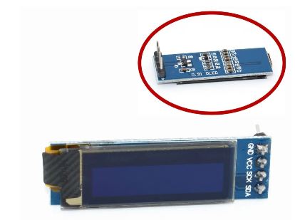
0.91 inch OLED
0.91 inch OLED module 0.91" white/Blue OLED 128X32 OLED LCD LED Display Module 0.91" IIC Communicate for Arduino

TFT
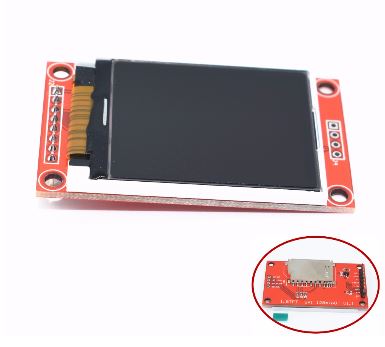
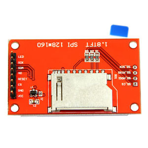
1.8 inch TFT LCD
1pcs 1.8 inch TFT LCD Module LCD Screen SPI serial 51 drivers 4 IO driver TFT Resolution 128*160 TFT interface 1.8 Inch


2.4" 2.4 inch TFT
2.4" 2.4 inch TFT 240*320 LCD Screen Module 5V/3.3V For Arduino UNO R3 Mega2560 Board Support STM32 C51 Micro SD Card ILI9341


SPI
Nokia 5110
For Arduino 84*48 Nokia 5110 LCD White/Blue Display Screen Module Module DIY AHS


http://anleitung.joy-it.net/?goods=lcd-modul-84x48-nokia-5110
Specification:
1. "LIGHT" linked with GND, the backlight to be lit.
2. Need you to compress the screen and PCB tighter, might got loose after the delivery.
3 Use a 3.3V controller, otherwise the display could be quite vague.
LCD5110 Module:
Power supply voltage:2.7V-3.3V,5V is OK,but part of the screen becomes black when tested
Data interface level:2.7-5V
Backlight power supply voltage:highest 3.3V
Installation diameter:2mm
Backlight:White
Document for Download:Data
1.RST--------- reset
2.CE------------chip selection
3.DC-----------data/commands choice
4.DIN-----------serial data line
5.CLK------------serial Clock Speed
6.3.3V------------VCC
7.LIGHT--------- backlight control terminal
8.GND-----------power negative
Features:
84 X 48 dot matrix LCD,can show 4 lines of characters
Use serial interface communicate with the master processor,the number of interface signal line reduced
greatly, only 8 signal lines including power and GND.Support different types of MCU,such as the SPI,
MCS51 serial mode 0 of AVR.Transfer rate up to 4Mbps,can full speed write display data without waiting time.
Can use the conductive glue to connect the module with the printed board,without connecting cable.The
metal hooks on the module can fix the module on the printed board,which is very easy to install and replace.
LCD controller/driver chip has been bound to LCD chip,the volume of LCD is small
Low power supply,the working current in normal situation is lower than 200μA,and has power-down mode.
Blue Backlights White Backlights
Bare Screen(NO PCB)
Controller Philp PCD8544 LCD controller .
input voltage :2.7-3.3v
can be driverd by Arduino/STM32/8051/AVR/PIC and other low power controllers
Compatible with Nokia 3310 LCD driving source code

NOTE:This item is only Nokia 5100 LCD bare screen without PCB pinboard
Package Included:
1*Nokia 5110 LCD Bare Screen 84*48 (NO PCB) for Arduino AVR PIC STM32
ST7735
1.44" Colorful SPI TFT LCD Display ST7735 128X128 Replace Nokia 5110/3310 AHS


Feature:
100% brand new and high Quality
1.44-inch screen with SPI serial backplane module, a minimum of only four IO-driven resolution 128 * 128
Spike NOKIA 5110, perfect upgrade true color
Size: 1.44 inch SPI serial bus
Resolution 128 * 128
ST7789
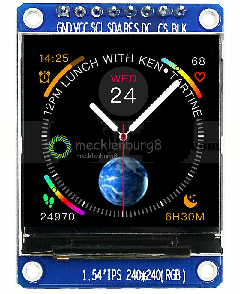
1.54 inch TFT IPS 240x240 SPI LCD Display Module for Arduino Raspberry Pi
.jpg)
Description
ER-TFTM1.54-1 is 240x240 pixel 1.54 inch IPS tft lcd display with ST7789 controller and breakout board,superior display quality,super wide viewing angle and easily controlled by MCU such as 8051, PIC, AVR, ARDUINO,ARM and Raspberry PI.It can be used in any embedded systems,industrial device,security and hand-held equipment which requires display in high quality and colorful image.It's 4-wire serial spi interface with pin header connection.
It's easily controlled by MCU such as 8051,PIC,AVR,ARDUINO,ARM and Raspberry Pi.It can be used in any embedded systems,industrial device,security,medical and hand-held device.

Of course, we wouldn't just leave you with a datasheet and a "good luck!" We prepared the interfacing documents,libraries and examples for arduino due,mega 2560,uno,nano and for 8051 microcontroller user,we also prepared the interfacing document and demo code.
Specification
Gross Weight (kg)	0.0220
Manufacturer	EastRising
Continuity Supply	We promise the long term continuity supply for this product no less than 10 years since 2019.
Part Number	ER-TFTM1.54-1
Display Format	240x240 Dots
Interface	4-Wire Serial SPI
IC or Equivalent	ST7789VW
Appearance	RGB
Diagonal Size	1.54"
Connection	Metal Pin
Outline Dimension	32.00(W)x43.72(H)
Visual Area	28.72x28.72mm
Active Area	27.72(W)x27.72(H)mm
Character Size	No
Dot (Pixel) Size	No
Dot (Pixel) Pitch	0.115x0.115mm
IC Package	COG
Display Type	TFT-LCD Color
Touch Panel Optional	No
Sunlight Readable	No
Response Time(Typ)	20ms
Contrast Ratio(Typ)	500:1
Colors	4K/65K/262K
Viewing Direction	No
Viewing Angle Range	Left:80.0, Right:80.0 , Up:80.0, Down:80.0degree
Brightness(Typ)	400cd/m2
Backlight Color	White Color
Backlight Current (Typ)	No
Power Supply(Typ)	2.8V
Supply Current for LCM(Max)	No
Operating Temperature	-20℃~70℃
Storage Temperature	-30℃~80℃
Series Number	ER-TFT1.54-1
https://thesolaruniverse.wordpress.com/2019/12/24/connecting-a-240x240-tft-display-with-st7789-controller-with-a-nodemcu-esp8266-or-an-arduino-nano/
https://simple-circuit.com/arduino-st7789-ips-tft-display-example/
https://educ8s.tv/arduino-st7789-tutorial/
https://www.arduinolibraries.info/libraries/adafruit-st7735-and-st7789-library

https://github.com/adafruit/Adafruit-ST7735-Library
https://github.com/cbm80amiga/Arduino_ST7789_Fast
https://github.com/cbm80amiga/ST7789_Watch_2bit/blob/master/ST7789_Watch_2bit.ino
Pegelwandler
Pegelwandler 5V 3,3V 4Kanal Level Shifter
http://www.ebay.de/itm/172110795634


8 Channel Logic Level Bi-directional Converter Module TXS0108E TXB0108 Arduino

TXB0108 bi-directional level converter comes in! This chip perform bidirectional level shifting from pretty much any voltage to any voltage and willauto-detect the direction. Only thing that doesn't work well with this chip is i2c (because it uses strong pullups which confuse auto direction sensor). If you need to use pullups, you can but they should be at least 50K ohm - the ones internal to AVRs/Arduino are about 100K ohm so those are OK! Its a little more luxurious than a 74LVX245 but if you just don't want to worry about directional pins this is a life saver!

Since this chip is a special bi-directional level shifter it does not have strong output pins that can drive LEDs or long cables, it's meant to sit on a breadboard between two logic chips! If you do not need instant bi-directional support, we suggest the 74LVX245 as below which has strong output drive

Features:
1.1.2V 1.8V 2.2V 2.5V 3.3V 5V Logic Level Bi-directional Converter Module
Features:
1.1.2V 1.8V 2.2V 2.5V 3.3V 5V Logic Level Bi-directional Converter Module
Package included:
1PCS x TXS0108E 8 Channel Logic Level Bi-directional Converter Module TXB0108 Arduino
Infrarot Empfänger
TSOP 1136 IR-Empfänger
http://pdf.datasheetcatalog.net/datasheets/restul/305097_DS.pdf
https://learn.adafruit.com/using-an-ir-remote-with-a-raspberry-pi-media-center?view=all
TSOP 4838 IR-Empfänger
Fernbedienung + HX1838 Empfänger + Codiert Infrarot modul


SPI
MCP3008
Analog-Digital Converter

RaspberryPi
http://tutorials-raspberrypi.de/raspberry-pi-mcp3008-analoge-signale-auslesen/
http://erik-bartmann.de/component/attachments/download/21.html
I2C
http://rn-wissen.de/wiki/index.php/I2C_Chip-%C3%9Cbersicht
PCF 8566
Dil-40 LCD-Treiber

PCF 8570
Dip-8 SRAM

PCF 8573
http://datentechniker2004.faxgate.org/ingo.goeppert/dt/projekte/i2c/dateien/pcf8573.pdf
PCF 8574 P I2C Port Expander
Philips I²C-Bus Port-Erweiterung DIP 16.


http://www.ti.com/lit/ds/symlink/pcf8574.pdf

https://www.mikrocontroller.net/articles/Port-Expander_PCF8574
PCF8575 IO Expander Tafel Modul I2C Bis 16 IO Zum Arduino Module GE
.jpg)
Overview:
Have you run out of I/O pins? This great module allows the user to expand up to 16 I/O using only two I/O for control! The PCF8575 is controlled through an I2C interface and features 16-bits of quasi-bidirectional input/output pins.
On board 3.3V level converter circuit, if you donot solder VCC-VDD pad, the PCF8575 level is 3.3V. If you solder it, the level will be the same with VCC.
Features:
- Arduino available library: PCF8575
- Working voltage: 2.5 - 5.5VDC
- Working current: 100mA(MAX)
- I2C address: 0x20(default),can be modified by soldering A1 and A2 selection pads.
- 16 individually addressable pins.
- Each pin configurable for input or output.
- Open-drain interrupt output pin for input change interrupt.
- Great for Arduino UNO R3 and other MCU to control simple relay, buzzer, button, led.
PCF 8582
Dip-8 I²C Bus EEPROM 256 Byte

PCF 8584 I2C-bus Controller
Dil-20 Interface

http://www.nxp.com/documents/data_sheet/PCF8584.pdf
PCF 8591

Dil-16 A/D-Wandler
YL-40 PCF8591 8 Bit Analog-Digital-Wandler ADC I2 C YL-40 Arduino

DS 1620
Thermometer, DIP-8
EEProms 24C02
PN532 NFC RFID
OLED Display

Ein 0,96 Zoll OLED Display I²C mit 128×64 Pixel und ein Arduino
http://blog.simtronyx.de/ein-096-zoll-oled-display-i%C2%B2c-mit-128x64-pixel-und-ein-arduino/
OLED i2c display with arduino
http://www.instructables.com/id/Monochrome-096-i2c-OLED-display-with-arduino-SSD13/?ALLSTEPS
Arduino OLED Display Library
https://oscarliang.com/arduino-oled-display-library/
https://github.com/wtfuzz/ssd1306_text
https://learn.adafruit.com/monochrome-oled-breakouts/overview
https://learn.adafruit.com/monochrome-oled-breakouts?view=all
TM1638 LED&Key

https://blog.3d-logic.com/2015/01/10/using-a-tm1638-based-board-with-arduino/
http://arduinolearning.com/learning/basics/arduino-tm1638-module.php
http://www.arduino-projekte.de/index.php?n=69
https://github.com/rjbatista/tm1638-library/wiki
DS3231
DS3231 AT24C32 IIC Modul Präzisions-Taktmodul

https://github.com/akafugu/WireRtcLibrary

https://github.com/NorthernWidget/DS3231
https://github.com/JChristensen/DS3232RTC
https://github.com/MrAlvin/RTClib
ZS-042 Real-time Clock Module - Blau DS3231


https://www.electronicshub.org/arduino-ds3231-rtc-module-tutorial/
DS3231 Real Time Clock Module für arduino 3,3 V/5 V mit batterie Für Raspberry Pi

Ein. Übersicht:
Raspberry Pi ausländischen höchste präzision uhr modul DS3231
Hinweis motherboards auch verwenden dieses modul.
Module können anzupassen selbst 3,3 V und 5V systeme ohne niveau umwandlung, dies ist ein super bequem!
Zwei. Eigenschaften:
Die 1.-40 ° C bis + 85 ° C temperatur bereich, timing genauigkeit gehalten zu ± 5ppm (± 0,432 sec/tag)
2 zeitgleich bieten kontinuierliche batterie-backup
3 low-power
4. gerät paket und funktion kompatibel mit die DS3231
5. komplette uhr kalender funktionen umfassen sekunden, minuten, stunden, tag, datum, monat und jahr timing und bieten gültig bis die jahr 2100 schaltjahr  entschädigung
6 zwei kalender alarm
7,1Hz und 32,768 kHz ausgang
8 reset-taste debounced eingang und ausgang
9-geschwindigkeit (400kHz) I2C serial bus
10. + 2,3 V bis + 5,5 V Liefern Spannung
11 ± 3 ° C genauigkeit digitale temperatur sensor
12.-40 ° C bis + 85 ° C betriebs temperatur bereich
13,16-pin SO (300mil) paket
14 durch Underwriters Laboratories (UL) zertifizierung
SRF 08 Ultraschall Abstandssensor


HC-SR04 Ultraschall Abstandssensor

Der HC-SR04 Sensor ist im eigentlichen Sinne kein Abstand/Bewegungsmelder, sondern ein Ultraschallsensor. Durch einen kleinen Trick ist es dennoch möglich Distanzen zu messen. Indem man die Zeit misst, welche zwischen Senden und Empfangen eines Ultraschallsignales vergangen ist, kann man sich die Distanz herleiten, da die Schallgeschwindigkeit in der Luft bekannt ist. Im Tutorial gehe ich sehr detailiert darauf ein. Ein Aspekt der allerdings beachtet werden muss ist der breite Öffnungswinkel: Da der Ultraschall sich nicht nur auf einer Geraden ausbreitet, sondern in einem Öffnungswinkel von ca. 15° wird das Signal als erstes vom nähesten Punkt in diesem Bereich reflektiert – was eben auch ein äußerer Punkt sein kann.
Als grobe Schätzung bzw. für fahrende Roboter eignet er sich dennoch gut, nicht zuletzt wegen den geringen Kosten.
https://tutorials-raspberrypi.de/entfernung-messen-mit-ultraschallsensor-hc-sr04/
MCP23017 I2C interface 16bit I/O Extension Module Pin Board IIC to GIPO Convert
.jpg)


1. Description:
This module is the 16 way IO extension module of the 12C interface, and built in the MCP23017 chip of MicroChip. The function of the chip is complete. Each IO can be arbitrarily configured as input or output, and a pull up resistor can be set, and the interrupt function can be enabled for the IO configured as input. The IO interface has a strong driving capacity, and the current and current can reach 25mA.
MCP23017 is a high-speed IIC interface. It supports the IIC frequency of 100KHz, 400KHz and 1.7MHz. The chip has 3 address pins, which can be set up for 8 different addresses. So 8 modules can be connected through two IIC buses to achieve up to 128 IO extensions.

This module is flexible in configuration and strong in driving ability. There are many parallel connections.
2. Parameters:
No. Parameter Value
1 Operating voltage 3.0V-5.5V
2 Drive chip MCP23017
3 Number of IO 16 (input, output, interruption)
4 Drive power supply 25mA1
5 12C frequency 100KHz, 400KHz, 1..7MHz
6 working temperature -40 Celsius -125  Celsius
7 Chip level Industrial grade
8 Parallel multiple Up to 8
9 Driver 51 and Arduino
10 Module size 65mm*19mm

3. Pin description:
No. Pin Function Remark
1 VCC Power source input 3.0V-5.5V
2 GND Power negative electrode 0V
3 SCL 12C clock line SCL connecting single chip IO pin or MCU 12C interface
4 SDA 12C data line SDA connecting single chip IO pin or MCU 12C interface
5 RST Chip reduction Low level effective, connecting MCU IO pin or unconnected
6 ITA GPIOA port interrupt output Connect MCU IO pin, without connection when interruption
7 ITB GPIOB port interrupt output Connect MCU IO pin, without connection when interruption
https://www.nikolaus-lueneburg.de/2015/11/mcp23017-i2c-io-port-expander/
https://wolles-elektronikkiste.de/portexpander-mcp23017
https://github.com/adafruit/Adafruit-MCP23017-Arduino-Library
https://github.com/blemasle/arduino-mcp23017
BMP180 Barometer


Unsere AZ-Delivery BMP180 Sensoren erfassen höchst präzise den Luftdruck und Temperatur – zusammen mit Ihrer hohen Auflösung und der geringen Leistungsaufnahme sind diese Sensor Module ideal für viele DIY- und Smarthome-Projekte.
Ob zur unterstützenden Höhenbestimmung für GPS, im Modellbau oder als Wetterstation, durch ein universelles Interface und die verbreiteten Bibliotheken für Arduino, Raspberry & Co. ist die Anwendung besonders komfortabel.
Die Sensoren wurden von Bosch bereits werksseitig kalibriert. Es stehen verschiedene Betriebsmodi zur Auswahl, von “ultra low power“ bis “ultra high resolution“.
In Wetterstationen und ähnlichen Projekten kann die Bestimmung der Luftdrucks aussagekräftig sein. Dazu verwendet man am besten den BMP180, welcher über I2C am Raspberry Pi angesteuert wird. Neben dem Luftdruck kann auch die Temperatur ausgelesen werden und außerdem die Höhenlage (Altitude). Allerdings ist die letzte Angabe nicht all zu genau. Falls man die Höhe braucht, sollte man lieber die Werte mit einem GPS Empfänger auslesen.
https://tutorials-raspberrypi.de/raspberry-pi-und-i2c-luftdrucksensor-bmp180/
BMP180 Digitaler Luftdruck Sensor GY-68 BMP085 Arduino Raspberry Barometer Modul
Technische Daten:
IC: BMP180
Betriebsspannung: 1,8V - 3,6V
Interface: I2C
Reaktionszeit: 7,5 ms
Stromverbrauch: 5µA, Standby: 0,1µA
Größe: ca. 14 mm x 12 mm
Gewicht: ca. 1,27 g
Beim BMP180 handelt es sich um einen digitalen und sehr präzisen Temperatur- und Luftdrucksensor. Er ist wesentlich genauer als sein Vorgänger BMP085 und eignet sich auf Grund seines niedrigen Stromverbrauchs bestens zur mobilen Anwendung.
BMP280 GY-BME280 Barometrischer Sensor für Temperatur, Luftfeuchtigkeit und Luftdruck


BMP280 Barometer / Luftdruck-Sensor ist ein sehr genaues Modul zum Messen von Luftdruck und ideal zum Bestimmen von Temperatur, Wetter, Flughöhe uvm.
Dieser Luftdruck-Sensor ist die beste low-cost Lösung für DIY-Projekte! Er basiert auf dem Bosch-Sensor BMP280 und ist wesentlich präziser und stromsparender als sein Vorgängermodell derBMP180, wodurch er sich auch als Upgrade anstelle der BMP085 und BMP183 Sensoren eignet.
Dank den kleinen Abmessungen von 3,6 x 3,8 x 0,93 mm und dem super niedrigen Stromverbrauch eignet sich dieses Modul hervorragend für mobile Geräte. Das Messen des Luftdrucks ermöglicht z.B. die Bestimmung der Höhenlage am Boden oder der Flughöhe eines RC-Multicopters.
Das Modul lässt sich mit I2C bzw. SPI ansteuern, eignet sich perfekt für Raspberry Pi Projekte und verfügt über eine Betriebsspannung von 1,8V bis 3,6V. Durch das gratis eBook 📖 zur Inbetriebnahme können Sie außerdem direkt loslegen!
SHT30-D
SHT30 SHT30-D Temperature Humidity Sensor Breakout
Sensiron Temperature/Humidity sensors are some of the finest & highest-accuracy devices you can get. And, finally we have some that have a true I2C interface for easy reading. The SHT30-D sensor has an excellent ±2% relative humidity and ±0.3°C accuracy for most uses.
Unlike earlier SHT sensors, this sensor has a true I2C interface, and (bonus!) even with two address options. It also is 3V or 5V compliant, so you can power and communicate with it using just about any microcontroller or microcomputer. Such a lovely chip - so we spun up a breakout board with the SHT30-D and some supporting circuitry such as pullup resistors and capacitors. Each order comes with one fully assembled and tested PCB breakout and a small piece of header. You'll need to solder the header onto the PCB but it's fairly easy and takes only a few minutes even for a beginner.
Power Pins:
Vin - this is the power pin. The chip can use 2.5-5VDC for power. To power the board, give it the same power as the logic level of your microcontroller - e.g. for a 5V micro like Arduino, use 5V. For a 3.3V controller like a Raspbery Pi, connect to 3.3V
GND - common ground for power and logic
I2C Logic pins:
SCL - I2C clock pin, connect to your microcontrollers I2C clock line.
This pin has a 10K pullup resistor to Vin
SDA - I2C data pin, connect to your microcontrollers I2C data line.
This pin has a 10K pullup resistor to Vin
Other Pins:
ADR - This is the I2C address selection pin. This pin has a 10K pull down resistor to make the default I2C address 0x44. You can tie this pin to Vin to make the address 0x45
RST - Hardware reset pint. Has a 10K pullup on it to make the chip active by default. Connect to ground to do a hardware reset!
ALR - Alert/Interrupt output. You can set up the sensor to alert you when an event has occured. Check the datasheet for how you can set up the alerts
SHT31-D

SHT31 GY-SHT31-D Temperature Humidity Sensor Breakout
Digitaler Feuchtesensor SHT3x (RH/T)
Leistungsstärkster Feuchtesensor für eine Vielzahl von Anwendungen
Die digitale Feuchtesensor-Serie SHT3x bringt Sensortechnologie auf ein neues Level und setzt als Nachfolger der erfolgreichen SHT2x Serie den Industriestandard in der Feuchtesensorik. Die Serie besteht aus einer preisgünstigen Version (Feuchtesensor SHT30), einer
Standardversion (Feuchtesensor SHT31) und einer Premiumvariante (Feuchtesensor SHT35). Die SHT3x-Serie kombiniert vielfältige Funktionen und variantenreiche Schnittstellen (I2C, Spannungsausgang) mit einem anwendungsfreundlichen, sehr breiten
Betriebsspannungsbereich (2.15 bis 5.5 V). Die Sensoren der SHT3x-Serie sind sowohl in grossen Volumina als auch in geringer Stückzahl erhältlich.
Der SHT3x basiert auf einem komplett neuen und optimierten CMOSens®-Chip, welcher eine verbesserte Zuverlässigkeit und Genauigkeit ermöglicht. Zudem bietet der Feuchtesensor SHT3x noch weitere Funktionalitäten wie etwa eine verbesserte Signalverarbeitung, zwei
unterschiedliche und benutzerdefinierbare I2C-Adressen, eine Alarmfunktion mit programmierbaren Feuchte- und Temperaturlimiten sowie Kommunikationsgeschwindigkeiten von bis zu 1 MHz.
Das Dual-Flat-no-Leads(DFN)-Gehäuse hat eine Grösse von 2.5 × 2.5 × 0.9 mm3. Somit lässt sich der Sensor einfach in eine Vielzahl von Anwendungen integrieren. Der breite Spannungsbereich von 2.15 V bis 5.5 V und die Vielzahl der erhältlichen Schnittstelle ermöglichen zudem Kompatibilität mit diversen Integrationssituationen. Zu guter Letzt enthält der neue Feuchtesensor SHT3x das gesammelte Know-how der 15-jährigen Erfahrung von Sensirion als Marktführer in der Feuchtesensorik.
Ausgabe: i2c, die Ausgangsspannung
Reaktionszeit der RH: 8 Sekunden (Tau63%)
Betriebstemperaturbereich: -40 ° bis 125 ° C (-40 ° bis 257 ° F)
RH-Betriebsbereich: 0-99,99% RH
Versorgungsspannung: 2,4 bis 5,5 V
Diymore I2C IIC INA226 Spannung Strom Power Monitor Modul Überwachung Alarm Alarm Funktion Bord Interface 36V Bi-Directional

Produkt Einführung:
1. gemeinsame Modus Spannung: 36 V (max)
2. Input Offset: 10uV (max)
3. Input Offset Drift: 0.02uV/C (typisch)
4. CMRR: 126dB (min)
5. bandbreite: 7 KHz
6. Supply Spannung: 5,5 V (max)
7. Operating Temperatur Bereich:-40 ~ 125 celsius
8. Special Features: alarm funktion; bi-directional; I2C; low-seite lage

Eigenschaften:
1. sinne Bus Spannungen Von 0 V bis 36 V
2. hohe-Seite oder-Low-Side Sensing
3. berichte Strom, Spannung, und Power
4. hohe Genauigkeit: 0.1% Gain Fehler (max)

Paket Enthalten:
1 x INA226 Bi-Directional Spannung Strom Power Alarm Monitor Modul
Solar power monitor
https://forum.arduino.cc/index.php?topic=678587.0
INA226 Strom- und Leistungssensor
https://wolles-elektronikkiste.de/ina226
Ein Batteriemonitor für Strom und Spannung mit dem INA226 und dem Arduino Uno 9 Antworten
http://shelvin.de/ein-batteriemonitor-fuer-strom-und-spannung-mit-dem-ina226-und-dem-arduino-uno/
Libs
https://github.com/peterus/INA226Lib
https://github.com/wollewald/INA226_WE
Full Color RGB LED Strip Driver Module Shield for Arduino STM32 AVR
.jpg)
Description:
1, on-board high-performance micro-controller chip
2, three-way onboard MOSFET, respectively, to control RGB three-color LED lights
3, the onboard power LED and reset button
4, the input and output power wiring board seat
5, onboard serial communication interface
6, the control board supply voltage :3.3-5 .0 V
7, PCB size: 37.2 (mm) x22.5 (mm)
LED control panel default communication baud rate is: 9600BPS

LED control panel communication protocol:
Data (1) --- Startup logo (default is 0x1F)
Data (2) --- channel number (1: red 2: green 3: blue)
Data (3) --- luminance value (0-100%)
Data (4) --- checksum (the sum of the first three data)

Example:
Set to automatically adjust light: 1F 00 00 1F
Red Light 1% brightness setting: 1F 01 01 21
Set the brightness of the red light 50%: 1F 01 32 52
Set the red light 99% brightness: 1F 01 63 83
Green light 1% brightness setting: 1F 02 01 22
Set the green light to 50% brightness: 1F 02 32 53
Set the green light to 99% brightness: 1F 02 63 84
Blue Light 1% brightness setting: 1F 03 01 23
Blue Light 50% brightness setting: 1F 03 32 54
Blue Light 99% brightness setting: 1F 03 63 85

Package Included:
1PC*Full Color RGB LED Strip Driver Module Shield for Arduino STM32 AVR
INA3221 3 Channel Shunt Current Voltage Monitor Sensor Replace INA219 Module w

Description
The INA3221 is a three-channel, high-side current and bus voltage monitor with an I2C- and SMBUS-compatible interface. The INA3221 monitors both shunt voltage drops and bus supply voltages, in addition to having programmable conversion times and averaging modes for these signals.
The INA3221 offers both critical and warning alerts to detect multiple programmable out-of-range conditions for each channel.
The INA3221 senses current on buses that can vary from 0 V to 26 V. The device is powered from a single 2.7-V to 5.5-V supply, and draws 350
µA (typ) of supply current. The INA3221 is specified over the operating temperature range of –40°C to +125°C. The I2C- and SMBUS-compatible
interface features four programmable addresses.
Features
Senses Bus Voltages From 0 V to 26 V
Reports Shunt and Bus Voltage
High Accuracy:
Offset Voltage: ±80 µV (max)
Gain Error: 0.25% (max)
Configurable Averaging Options
Four Programmable Addresses
Programmable Alert and Warning Outputs
Power-Supply Operation: 2.7 V to 5.5 V
https://forum.switchdoc.com/thread/1151/ina3221-arduino
ICs
NE555
http://www.elektronik-kompendium.de/sites/bau/0206115.htm
https://www.elektronik-kompendium.de/sites/slt/0310131.htm
http://www.kreatives-chaos.com/artikel/ne555-grundschaltungen
http://houseofjeff.com/555-timer-oscillator-frequency-calculator/
https://de.wikipedia.org/wiki/NE555

NE555 Adjustable Frequency Pulse Generator Modul NE555

SN76489AN


SN76489 Sound Generator Chip
https://silicon-heaven.org/howel/parts/76489.htm
Funktioniert
https://github.com/tyrkelko/sn76489

***************************************************************************
***** Directly interface SN76489 IC with the following PIN definitions *****
***** and by calling 8-bit constractor                                 *****
***** The SN76489 pinout considered for this library is as follows:    *****
*****                                                                  *****
*****                        ========                                  *****
*****        D2       --> [ 1]  ()  [16] <-- VCC                       *****
*****        D1       --> [ 2]      [15] <-- D3                        *****
*****        D0       --> [ 3]  7   [14] <-- CLOCK OSC                 *****
*****     READY       <-- [ 4]  6   [13] <-- D4                        *****
*****    NOT WE       --> [ 5]  4   [12] <-- D5                        *****
*****    NOT CE       --> [ 6]  8   [11] <-- D6                        *****
***** AUDIO OUT       <-- [ 7]  9   [10] <-- D7                        *****
*****       GND       --> [ 8]      [ 9] --- N.C.                      *****
*****                        ========                                  *****
***************************************************************************/
#define PIN_D0 2//13
#define PIN_D1 3//12
#define PIN_D2 4//A5
#define PIN_D3 5//A4
#define PIN_D4 6//A3
#define PIN_D5 7//A2
#define PIN_D6 8//A1
#define PIN_D7 9//A0
SN76489 mySN76489 = SN76489(PIN_NotWE, PIN_D0, PIN_D1, PIN_D2, PIN_D3, PIN_D4, PIN_D5, PIN_D6, PIN_D7, FREQUENCY,255);

https://akuzechie.blogspot.com/2021/07/sn76489-digital-sound-generator.html
SN76489AN
https://ftp.whtech.com/datasheets%20and%20manuals/Datasheets%20-%20TI/SN76489.pdf
https://segaretro.org/SN76489
https://en.wikipedia.org/wiki/Texas_Instruments_SN76489
SN76489 Digital Sound Generator Programming via Arduino
https://www.youtube.com/watch?v=gkgWgLmYFnE
https://akuzechie.blogspot.com/2021/07/sn76489-digital-sound-generator.html
Retro Sound Tech - Programming the SN76489 Sound Generator
https://www.youtube.com/watch?v=D0wh5Cyvj8E
https://github.com/thaaraak/SN76489-Tester
GITHub
https://github.com/tyrkelko/sn76489
https://github.com/MajicDesigns/MD_SN76489
https://www.youtube.com/watch?v=t6-9bIfuJvc
https://majicdesigns.github.io/MD_SN76489/page_hardware.html
http://www.vgmpf.com/Wiki/images/7/78/SN76489AN_-_Manual.pdf
http://danceswithferrets.org/geekblog/?p=93
https://www.arduino.cc/reference/en/libraries/sn76489/
https://arduinoplusplus.wordpress.com/2019/10/05/making-noise-with-a-sn76489-digital-sound-generator-part-1/
https://arduinoplusplus.wordpress.com/2019/10/19/making-noise-with-a-sn76489-digital-sound-generator-part-2/
https://arduinoplusplus.wordpress.com/2019/11/03/making-noise-with-a-sn76489-digital-sound-generator-part-3/
https://shepherdingelectrons.blogspot.com/2020/04/sn76489-midi-player.html
Verstärker
LM386
Verstärker
https://bwir.de/miniverstaerker-mit-dem-lm386/
https://easyeda.com/editor#id=!1ea8159a6dd547beb6d92709442f6efc
https://therepaircafe.wordpress.com/2017/03/23/kicad-3-lm386-amplifier-with-bass-boost/
Modul

LM386 Sound Verstärker
Mittels des LM386 Verstärker können Sie einen Lautsprecher oder Mikrofon am Arduino anschließen. Sehr hohe Verstärkung, dank des integrierten LM386 Amplifiers.
Technische Daten:
Onboard Chip LM386
On-Board-Lautsprecherkabel-Block
einstellbare Onboard Netzanzeige
die Chip-Pin-Anschlüsse können Audio-Eingangssignal direkt
Betriebsspannung: 5 ~ 12V
Abmessungen: 41 (mm) x13 (mm)
TBA810AS
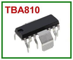

Busch Verstärker IC Baustein
https://datasheetspdf.com/pdf-file/1148369/SGS/TBA810P/1
https://bwir.de/preiswerter-7-watt-verstaerker-mit-dem-tba-810-a-210-k/

http://electronicsjmbh.blogspot.com/2012/11/tba810-integrated-circuit.html
A210K
A210K , 6W NF-Verstärker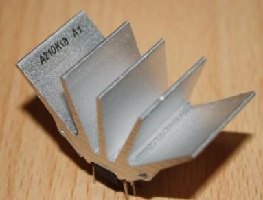


http://bilder.hifi-forum.de/max/481960/a210k-grundschaltung_208117.jpg
TCA830

https://html.alldatasheet.com/html-pdf/26395/TFUNK/TCA830/125/1/TCA830.html
https://datasheetspdf.com/datasheet/TCA830.html
https://www.mikrocontroller.net/topic/365107
Module
MINI L293D Arduino Motorantrieb Erweiterungskarte Mini L293D Motorantrieb Modul Deek Robot Motor Shield V1
 https://coderdojo-robots.readthedocs.io/en/latest/motor-direction-testing/
3 in 1 Remote Control + HX1838 Receiver + Coded Infrared Module with Female to Female Dupond Line Wire Cable Free Shipping

HC-SR501 Body Sensor Module Adjust IR PIR Pyroelectric Infrared PIR Motion Human Sensor Detector Module For Arduino

Der PIR Bewegungssensor hat einige Vorteile gegenüber anderen ähnlichen Produkten: Neben dem geringen Preis wird ein Signal erst dann gesendet, sobald sich etwas bewegt. Dadurch kann man auf Signal-Flanken mittels den GPIOs warten. Außerdem kann dabei ein Widerstand variiert werden, sodass nur noch bei nahen Bewegungen ein Signal gesendet wird oder eben bereits weit entfernte Änderungen wahrgenommen werden.
Neben Außenbereich-Projekten kann der PIR auch wunderbar in Gebäuden verwendet werden – sei es zum Aktivieren der Beleuchtung oder, wie ich es verwende, zum Einschalten meines Touchscreens zur Hausautomatisierung sobald jemand sich ihm nähert.
https://tutorials-raspberrypi.de/raspberry-pi-bewegungsmelder-sensor-pir/
BV4221
USB nach I2C
RS232-TTL
HC-05


https://www.itead.cc/wiki/Serial_Port_Bluetooth_Module_(Master/Slave)_:_HC-05
ftp://imall.iteadstudio.com/Modules/IM120723009/DS_IM120723009.pdf
https://www.az-delivery.de/blogs/azdelivery-blog-fur-arduino-und-raspberry-pi/hc-05-bluetooth-modul-einfuhrung?ls=de&cache=false
https://howtomechatronics.com/tutorials/arduino/arduino-and-hc-05-bluetooth-module-tutorial/
http://shelvin.de/das-bluetooth-modul-hc-05-mit-at-kommandos-vom-arduino-programmieren/
https://exploreembedded.com/wiki/Setting_up_Bluetooth_HC-05_with_Arduino
https://exploreembedded.com/wiki/images/a/a5/HC_05_Core_Datasheet.pdf
http://www.rasmicro.com/Bluetooth/EGBT-045MS-046S%20Bluetooth%20Module%20Manual%20rev%201r0.pdf
https://www.itead.cc/wiki/Serial_Port_Bluetooth_Module_(Master/Slave)_:_HC-05
https://igniteinnovateideas.wordpress.com/2016/04/18/arduino-bluetooth-basic-tutorial/

https://arduino-hannover.de/2013/07/20/bluetooth-kochbuch-fur-arduino/
https://forum.arduino.cc/index.php?topic=544399.0
https://draeger-it.blog/android-bluetoothkommunikation/
BlueSmirf


http://www.lynxmotion.com/images/html/build125.htm
http://www.electronics123.net/amazon/datasheet/RN-41.pdf
https://learn.sparkfun.com/tutorials/bluetooth-basics
http://ww1.microchip.com/downloads/en/DeviceDoc/rn-41-ds-v3.42r.pdf
https://www.digikey.com/eewiki/display/Wireless/Getting+Started+with+RN42+Bluetooth+Module
https://www.sparkfun.com/datasheets/Wireless/Bluetooth/rn-bluetooth-um.pdf
https://www.multitech.com/documents/publications/manuals/s000360i.pdf
http://www.cse.dmu.ac.uk/~eg/tele/sonyat.pdf
https://www.sparkfun.com/datasheets/RF/BlueRadios_AT_Commands_Rev_2.8.1.4.0.pdf
http://www.spezial.cz/pdf/Serial_Port_Adapter_AT_Commands.pdf
http://www.blueradios.com/software_SmartPhoneApps.htm
RFM12
Tastenfeld
Arduino Keypad Pinout
http://premiumandroid.com/2019/01/27/arduino-keypad-pinout/
3x4

MULTICOMP MCAK304NBWB Tastenfeld, 20 mA, 24 V, 3 x 4, Matrix, 12
The MCAK304NBWB is a 3 x 4 matrix plastic keypad.
•Actuating force of 100 ±30g
•Contact rating of 20mA at 24VDC
•Maximum contact resistance of 200 ohm
•10,00,000 cycles per key life
•Operating temperature range -20°C to +60°C
http://learning.grobotronics.com/2014/03/read-keypad-arduino-i2c/
http://playground.arduino.cc/Main/KeypadTutorial
http://playground.arduino.cc/Main/I2CPortExpanderAndKeypads
https://z4ziggy.wordpress.com/2014/06/13/arduino-keypad-with-1-analog-pin/
TTP224 4 Schlüssel Buttons Touch-Switch-Modul Touch-Kapazität Digital-Wandler Vorstand Sensor 2,4V-5,5V

TTP226 8-Kanal-kapazitiver Schalter Digital Touch Sensor Board-Modul für Arduino

TTP229 16-Channel Digitaler Touch Kapazitiver Sensor Modul XD-62B TTP229

Arduino

https://github.com/arduino12/ttp229-arduino
4x4

Folientastatur mit i2C Portexpander PCF8574
https://www.bastelgarage.ch/index.php?route=extension/d_blog_module/post&post_id=8
ESP Easy Tastatur und PCF8574
https://www.letscontrolit.com/forum/viewtopic.php?t=3845
I2C

SD Card
Micro SD Card Module


Onboard pop-up MINI sd-karte interface
Die verwandte pins sind bereits getan elicit und anmerkungen
Board größe: 18,5 (mm) x 17,5 (mm)

Paket Enthalten:
1 x Micro SD Speicher Expansion Board Mini Micro-SD TF Karte Memory Shield Modul Mit Pins ARM AVR
Mini Datenlogger Modul Protokollierung Schild für Arduino Für Raspberry Pi Protokollierung Recorder Datenlogger Modul Schild V1.0 SD Karte

Hinweis: Batterie ist CR1220 3 V, wir schiff ohne batterie! Hoffe, sie verstehen können.
Beschreibung:
Hier ist eine handliche eine rduino schild: wir 've hatte eine menge leute suchen für eine gewidmet und gut gestaltete daten logging schild. Wir hart gearbeitet, um design eine preiswert, aber design. Nicht nur ist es einfach zu montieren und anpassen, auch ausgestattet mit umfangreichen dokumentation und bibliotheken.
Sie können erhalten schnelle-zu speichern sie die daten einer datei in jede FAT16 oder FAT32 formatiert SD karte, sie können lesen jede zeichnung, tabellenkalkulation oder analyse programm. Wir haben sogar ein beispiel wie zu verwenden zwei freies software programme zu grundstück ihre daten tutorials
Einschließlich real-time clock mit der aktuellen zeit stempel für alle die daten, so dass sie genau wissen, was passiert, wenn!
Bitte beachten sie, dass dieser artikel nicht kommen mit einer rduino (sie verwenden müssen die schild), oder sd-karte. Es hat die RTC batterie, jedoch. Jetzt, die geologie von feuer zu alle komponenten der schweiß und prüfung, aber nicht installiert kopf. Sie müssen einige grundlegende löten fähigkeiten zu setzen es zusammen, aber auch wenn sie tun nicht haben viel erfahrung, können sie es innerhalb von 15 minuten zu komplette
Sd-karte interface mit FAT16 oder FAT32 formatiert karte. 3,3 V level shifter schaltung zu verhindern schäden an ihrem SD karte
Real-time clock (RTC) zu halten die zeit, auch wenn die eine rduino ist unplugged. Backup batterie dauerte für viele jahre
Einschließlich SD karte und RTC bibliotheken und probe code bedeutet sie können erhalten schnelle
Geschweißte gelenke, schaltungen oder sensoren prototyping bereich.
Eingebaute 3,3 V regler ist eine zuverlässige referenz spannung, und eine zuverlässige bedienung, erfordert eine menge power zu laufen die SD karte
Kompatibel mit eine rduino UNO, Duemilanove, Diecimila, Leonardo oder ADK/Mega R3 oder höher. ADK/MEGA R2 oder niedriger ist nicht unterstützt.
Paket Enthalten:
1 X Mini Daten Logger
PC817 Optokoppler
PC817 2 4 8 Kanal Optokoppler Isolation Bord Spannung Konverter Adapter Modul 3,6-30V Fahrer Photoelektrischen Isoliert Modul


Sensoren
50 DER WICHTIGSTEN RASPBERRY PI SENSOREN UND MODULE
http://tutorials-raspberrypi.de/raspberry-pi-sensoren-uebersicht-die-50-wichtigsten-module/
Infrared Reflective Photoelectric Switch TCRT5000 Ir Barrier Line Track Senso io


https://draeger-it.blog/arduino-lektion-59-infrarot-abstandssensor/?cn-reloaded=1
http://arduinolearning.com/code/tcrt5000-reflective-optical-sensor-module-example.php
https://osoyoo.com/2017/07/25/tcrt5000-ir-track-sensor/
YL-40 PCF8591 8 Bit Analog-Digital-Wandler ADC I2 C YL-40 Arduino
Luftqualität
Luftdruck HP03S I2C
http://digitalradiomondiale.blogspot.de/2012/06/hp03s-luftdruck-temperatursensor-mit.html
http://spurtikus.de/basteln/datalogger/

Luftfeuchte HH10D
https://tushev.org/articles/arduino/6/interfacing-hh10d-with-arduino

DHT11 / DHT22 AM2302


Die Sensoren DHT11 und DHT22 können neben der Temperatur auch die Luftfeuchtigkeit messen. Dabei wird nur ein GPIO belegt. Der Unterschied zwischen beiden ist vor allem die Messweite und die Genauigkeit. Der weiße DHT22 kann alle Luftfeuchtigkeitsbereiche von 0-100% messen und hat dabei eine Genauigkeit von 2%. Im Vergleich sind mit dem DHT11 (blau) lediglich Bereiche von 20-90% Luftfeuchte messbar, aber vor allem die Genauigkeit ist mit 5% deutlich schlechter. Einzig preislich hat der hellblaue DHT11 Sensor einen kleinen Vorteil (ca. einen Euro).
Arduino
https://github.com/nethoncho/Arduino-DHT22

http://www.buildcircuit.com/arduino-and-am2302-dht22-on-a-mini-breadboard/
http://www.arduino-tutorial.de/2014/01/temperatur-und-luftfeuchtigkeit-messen/
http://www.dfrobot.com/wiki/index.php/DHT22_Temperature_and_humidity_module_SKU:SEN0137
https://arduino-info.wikispaces.com/DHT11-Humidity-TempSensor
https://arduino-info.wikispaces.com/TemperatureHumidity

Raspberry Pi
https://tutorials-raspberrypi.de/raspberry-pi-luftfeuchtigkeit-temperatur-messen-dht11-dht22/
http://christian-ohmer.de/page/wiki/doku.php?id=wiki:sensoren:dht22
https://www.sweetpi.de/blog/436/luftfeuchtigkeit-und-temperatur-mit-dem-raspberry-pi-messen
https://klenzel.de/1827
http://wiki.volkszaehler.org/dht22
https://www.sweetpi.de/blog/436/luftfeuchtigkeit-und-temperatur-mit-dem-raspberry-pi-messen

CCS811 CJMCU-811
CJMCU CCS811 811 Carbon Monoxide CO Cov Gas Sensors Air Quality Numerical Module


https://cdn.sparkfun.com/assets/learn_tutorials/1/4/3/CCS811_Datasheet-DS000459.pdf
https://iotspace.dev/arduino-co2-sensor-im-eigenbau-ccs811-sensor/

https://learn.adafruit.com/adafruit-ccs811-air-quality-sensor/arduino-wiring-test
https://github.com/adafruit/Adafruit_CCS811

https://how2electronics.com/monitor-ccs811-co2-tvoc-on-esp8266-esp32-webserver/
https://github.com/maarten-pennings/CCS811
https://github.com/sparkfun/SparkFun_CCS811_Arduino_Library
CO2-Sensor MH-Z19B


https://unsinnsbasis.de/co2-sensor-mhz19b/
https://github.com/crisap94/MHZ19
https://www.blog.berrybase.de/blog/2021/02/16/diy-co2-ampel-mit-dem-mh-z19c/
https://esp8266-server.de/CO2Ampel.html
PM 2.5


https://github.com/openairproject/sensor-esp32
https://circuitdigest.com/microcontroller-proejcts/iot-based-air-quality-index-monitoring-system-measure-pm25-pm10-co-using-esp32
https://blog.kylemanna.com/hardware/sniffer-air-quality-monitor-aqi-using-esp32-pmsa003-bme680/
http://geekfem.net/other_uploads/Bub_final.pdf
https://www.electronicsforu.com/electronics-projects/esp32-based-air-quality-monitoring-system
GP2Y1014AU0F Compact Optical Dust Sensor


http://arduinodev.woofex.net/2012/12/01/standalone-sharp-dust-sensor/
http://qqtrading.com.my/optical-dust-sensor-gp2y1010au0f-sharp
3 Achsen Beschleunigung MEMS1


GY-521 3 Achsen MPU-6050 Beschleunigungssensor / Gyroskop / Accelerometer
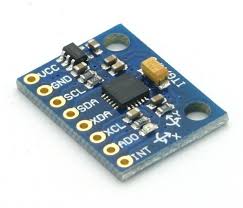


https://tutorials-raspberrypi.de/raspberry-pi-mpu-6050-rotationssensor-webgl-nodejs-server/
https://www.hackster.io/Nicholas_N/how-to-use-the-accelerometer-gyroscope-gy-521-6dfc19
X9C103S Digital Potentiometer Board Module DC3V-5V for Arduino 10K Span Potentiometer


https://www.instructables.com/X9C103P-Basic-Operation/
https://sites.google.com/site/tfagerscode/home/digipotx9cxxx
https://www.arduino.cc/en/Tutorial/LibraryExamples/DigitalPotentiometer

https://protosupplies.com/product/x9c103s-digital-potentiometer-module/
https://www.instructables.com/2-Button-Digital-Potentiometer-X9c104/
Kompassmodul HDMM01
http://www.mtahlers.de/index.php/elektronik/sensoren/mmc2120mg
http://www.aurob.com/?p=467
http://chris.cnie.de/avr/arduino-hdmm01.html

Flexsensor 2.2

CODE
#include <Servo.h>
Servo myservo; // create servo object to control a servo
int potpin = 0; // analog pin used to connect the potentiometer
int val;// variable to read the value from the analog pin
void setup()
{
Serial.begin(9600);
myservo.attach(9); // attaches the servo on pin 9 to the servo object
}
void loop()
{
val = analogRead(potpin);
between 0 and 1023)
Serial.println(val);
val = map(val, 50, 300, 0, 179);
and 180)
myservo.write(val);
value
delay(15);
}
// reads the value of the potentiometer (value
// scale it to use it with the servo (value between 0
// sets the servo position according to the scaled
// waits for the servo to get there
37-IN-1-SENSOR-KITS-FOR-ARDUINO

http://de.aliexpress.com/item/37-IN-1-SENSOR-KITS-FOR-ARDUINO-HIGH-QUALITY-FREE-SHIPPING-Works-with-Official-for-Arduino/32649847420.html#extend
sensorkit.joy-it.net
https://sensorkit.joy-it.net/de/
Arduino
https://www.elektor.de/arduino-sensor-kit
RaspBerryPi
http://tutorials-raspberrypi.de/raspberry-pi-gas-sensor-mq2-konfigurieren-und-auslesen/
KY-001 DS18B20

Temperature Sensor Module DS18B20
This module measures the temperature and reports it through the 1-wire bus digitally to the Arduino.
Einen sehr einfachen Sensor stellt der DS18B20 bzw. DS18S20 dar. Diese Raspberry Pi Sensoren werden über den sog. 1-Wire Bus angesprochen. Ein Vorteil besteht darin, dass viele verschiedene 1-Wire Bauteile hintereinander angeschlossen werden können und mittels eines einzigen GPIOs ausgelesen werden. Allerdings können diese Module keine zusätzlichen Infos wie Luftfeuchtigkeit und/oder Luftdruck messen. Dafür eignet sich der DS18B20 besonders im Außenbereich, da es auch wasserfeste Versionen zu kaufen gibt. Mit einem Messbereich von -55°C bis +125°C ist er selbst für nicht alltägliche Anwendungen gut geeignet.
https://tkkrlab.nl/wiki/Arduino_KY-001_Temperature_sensor_module
https://tutorials-raspberrypi.de/raspberry-pi-temperatur-mittels-sensor-messen/


KY-002
Shock Sensor Module
This module is digital shock sensor. It will output a high level signal when it detects a shock event.

KY-003 HALL MAGNETIC SENSOR MODULE

Hall Magnetic Field Sensor Module
This module can be used to detect the presence of an magnetic field. If there is an magnetic field present, it will report a high level signal.

https://www.az-delivery.de/products/hall-sensor-modul-digital
KY-004 Button
Momentary Button Module
This is a button module. When the button is pressed, it will a high level signal.

KY-005
Infrared Transmitter Module
This is an infrared transmitter module that is used to emit infrared signal.

KY-006 Buzzer
Buzzer Module
This is an active buzzer module that can make different sound.

YL-44
Buzzer Module


KY-007
KY-008 Laser
Laser Diode Module
This is a laser emitter diode. The working voltage is 5V, with a wavelength of 650nm.

KY-009 3C LED
3-color full-color LED SMD modules

KY-010
Optical broken module

KY-011
2-color LED module

KY-012

KY-013

KY-014
KY-015 Temp/Hum

KY-016

KY-017

KY-018 FotoR

KY-019 Relay

KY-020

KY-021

KY-022

KY-023

KY-024 Linear magnetic Hall Sensor
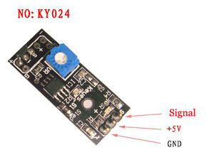

http://sensorkit.joy-it.net/index.php?title=KY-024_Linear_magnetic_Hall_Sensor
KY-025

KY-026

KY-027

KY-028

KY-029
KY-030
KY-031

KY-032

KY-033

KY-034

KY-035 magnetischer Hall Sensor Modul
KY-035 Bihor magnetic sensor module


https://www.az-delivery.de/products/copy-of-hall-sensor-modul-analog
https://sensorkit.joy-it.net/index.php?title=KY-035_Bihor_Magnet_Sensor_Modul
KY-036

KY-037

KY-038

KY-039

KY-040 Rotary Encoder
http://henrysbench.capnfatz.com/henrys-bench/arduino-sensors-and-input/keyes-ky-040-arduino-rotary-encoder-user-manual/

WIKI
https://tkkrlab.nl/wiki/Arduino_37_sensors
http://linksprite.com/wiki/index.php5?title=Advanced_Sensors_Kit_for_Arduino
Gas Sensoren MQ

https://github.com/miguel5612/MQSensorsLib
MQ-2
MQ-2 Sensitive for Methane, Butane, LPG, smoke. This sensor is sensitive for flamable and combustible gasses.
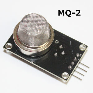

https://blog.moneybag.de/gassensor-mq-7-mit-lcd-display-und-arduino-nano/
Die MQ Gas Sensoren können verschiedene Gase bei Raumtemperatur erkennen. Je nach Modell werden andere Gase unterstützt. Der übliche MQ-2 Sensor kann Methan, Butan, LPG und Rauch erkennen, der MQ3 erkennt bspw. Alkohol, Ethanol und Rauch, usw. Eine Auflistung aller MQ Sensoren und deren unterstützte Gase kann hier (deutsch bzw. englisch) eingesehen werden.
Es sollte dabei darauf geachtet werden, dass diese Sensoren sehr heiß werden können und man sie daher nicht direkt anfassen sollte. Da diese Module auch analog mit 5V arbeiten, ist auch hier ein MCP3008 sowie ein 3.3V-5V TTL zum Auslesen der Signale nötig.
https://tutorials-raspberrypi.de/raspberry-pi-gas-sensor-mq2-konfigurieren-und-auslesen/
https://blog.moneybag.de/mq-2-sensor-und-luftqualitaets-sensor-ein-vergleich/
MQ-3
MQ-3 Sensitive for Alcohol, Ethanol, smoke

MQ-4
MQ-4 Sensitive for Methane, CNG Gas

MQ-5
MQ-5 Sensitive for Natural gas, LPG

MQ-6
MQ-6 Sensitive for LPG, butane gas

MQ-7
MQ-7 Sensitive for Carbon Monoxidehttps://blog.moneybag.de/gassensor-mq-7-mit-lcd-display-und-arduino-nano/
MQ-8
MQ-8 Sensitive for Hydrogen Gas

MQ-9
MQ-9 Sensitive for Carbon Monoxide, flammable gasses.

MQ-135
MQ-135 For Air Quality. Sensitive for Benzene, Alcohol, smoke.

http://playground.arduino.cc/Main/MQGasSensors
https://disqus.com/home/discussion/mysensors/mysensors_gas_sensor_89/
https://community.particle.io/t/mq135-and-spark-core/12657
https://github.com/empierre/arduino
https://github.com/empierre/arduino/blob/master/AirQuality-MQ135.ino
https://gleisnetze.de/2015/12/25/das-erste-kleine-programm/
https://gleisnetze.de/2016/02/06/sensor/
https://www.mysensors.org/build/gas
Links
http://de.aliexpress.com/store/product/for-Arduino-Diy-Starter-1set-Gas-Detection-Sensor-Module-MQ-Kit-MQ-2-MQ-3-MQ/1757110_32349408775.html
http://playground.arduino.cc/Main/MQGasSensors
https://blog.moneybag.de/gassensor-mq-7-mit-lcd-display-und-arduino-nano/
http://www.instructables.com/id/How-to-use-MQ2-Gas-Sensor-Arduino-Tutorial/?ALLSTEPS

http://www.instructables.com/id/How-to-use-MQ2-Gas-Sensor-Arduino-Tutorial/
http://www.seeedstudio.com/wiki/How_to_choose_A_Gas_Sensor
https://blog.moneybag.de/gassensor-mq-7-mit-lcd-display-und-arduino-nano/
https://github.com/empierre/arduino/blob/master/AirQuality-MQ135.ino
http://davidegironi.blogspot.de/2014/01/cheap-co2-meter-using-mq135-sensor-with.html#.V7hyrE3wC9I
https://forum.mysensors.org/topic/147/air-quality-sensor
Pulsesensor

http://de.aliexpress.com/store/product/Free-shipping-pulsesensor-pulse-heart-rate-sensor-for-Arduino-open-source-hardware-development-pulse-sensor/1280487_32582700771.html?storeId=1280487
http://pulsesensor.com/
Raspberry Pi
http://tutorials-raspberrypi.de/raspberry-pi-puls-herzfrequenz-messen/
Sensormodul Regen Wetter Modul

Feuchtigkeitssensor

Dieser analoge Feuchtigkeitssensor findet einen hervorragenden Platz in automatischen Bewässerungssystemen. Dabei wird er in die Erde gesteckt und misst die Feuchtigkeit, indem zwischen den Strängen ein Strom fließt. Umso feuchter die Erde dazwischen ist, umso höher ist das (analoge) Signal. Um den Wert mit dem Raspberry Pi auslesen zu können, wird noch der MCP3008 benötigt (Arduinos können analoge Signale direkt erkennen).
https://tutorials-raspberrypi.de/bodenfeuchtigkeit-mit-dem-raspberry-pi-messen/
SHARP IR Ranger Sensor GP2D12
Introduction

The Sharp GP2D12 is an analog distance sensor that uses infrared to detect an object between 10 cm and 80 cm away. The GP2D12 provides a non-linear voltage output in relation to the distance an object is from the sensor and interfaces easily using any analog to digital converter.
Specification
- Measuring range : 10 to 80 cm
- The maximum allowable Angle : > 40 °
- The power supply voltage : 4.5 to 5.5 V
- The average power consumption : 35 mA
- Peak power consumption : about 200 mA
- The frequency of updates/cycle : 25 Hz/40 ms
- Analog output noise : < 200 mV
Document
Pinout

Usage
Here is the guide illustrates how to connect an Arduino to the ADXL335 breakout board.


Example code
char GP2D12;
char a,b;
void setup()
{
 Serial.begin(9600); //
}
void loop()
{
 int val;
 GP2D12=read_gp2d12_range(0);
 a=GP2D12/10;
 b=GP2D12%10;
 val=a*10+b;
 if(val>10&&val<80)
 {
   Serial.print(a,DEC);//
   Serial.print(b,DEC);//
   Serial.println("cm");//
 }
 else Serial.println("over");//
 delay(50);
}
float read_gp2d12_range(byte pin)
{
 int tmp;
 tmp = analogRead(pin);
 if (tmp < 3)return -1;
 return (6787.0 /((float)tmp - 3.0)) - 4.0;
}
How to buy
Click here to buy SHARP IR Ranger Sensor GP2D12
Fingerprint Sensor


Color: Black + green
Material: Plastic + component
Working frequency: 433Mhz/868Mhz/915Mhz
Sensitivity: -100dBm
Working voltage: 1.9~3.6V,
Operating rate: 50Kbps,
Supply voltage: DC 3.6~6.0V
Character file size:256 bytes
Template size:512 bytes
Storage capacity:1000
Search time: < 1 second
False Acceptance Rate (FAR) < 0.001%
False Rejection Rate (FRR) < 1.0% (security level: 3)
Voltage 3.6-6.0V DC via USB port
Working current: < 120mA
Peak voltage: < 140mA
Window size: 14 x 18mm
Upstream: UART: (9600×N)bps (N=1~12, N default 6, equal 57600bps)
Operating environment Temperature: -20 to 50 centigrades
Relative humidity: 40%RH to 85%RH (No condensation)
During the fingerprint verification process, the latest collected fingerprint features would be integrated into the fingerprint database automatically so that the users would  obtain better and better fingerprint verification result.
Can be embedded into a variety of end products, such as: access control, attendance, safe, car door locks.
Arduino Lib
https://github.com/adafruit/Adafruit-Fingerprint-Sensor-Library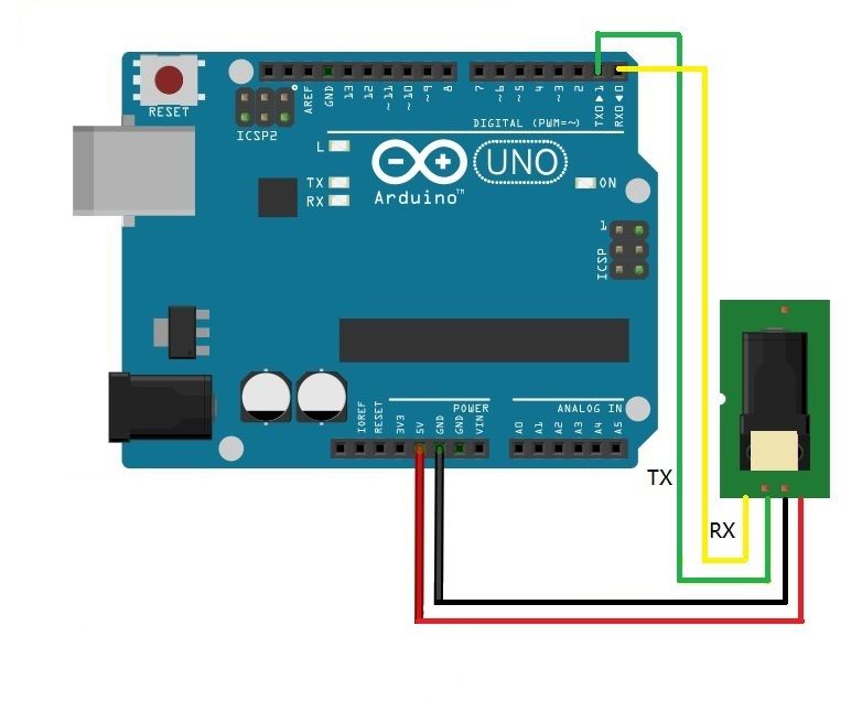

Tutorial
https://learn.adafruit.com/adafruit-optical-fingerprint-sensor
https://learn.adafruit.com/adafruit-optical-fingerprint-sensor/downloads
https://learn.adafruit.com/adafruit-optical-fingerprint-sensor/enrolling-new-users-with-windows
GY-471 MAX471 3A Palette Aktuelle Sensor Modul Professionelle MAX471 Modul Für Arduino


Beschreibung:
Größe: 19,5*20,3mm
Dieses modul kann verwendet werden, um die strom und spannung.
Die prinzip von spannung test basiert auf prinzip von resistiven spannung teiler design, kann machen das rote terminal stecker eingang spannung zu 5 mal kleiner. Analog eingang spannungen bis zu 5 v, die spannung erkennung modul eingang spannung nicht größer als 5Vx5 = 25 V (wenn mit 3,3 V systeme, eingang spannung nicht größer als 3.3Vx5 = 16,5 V). AVR chips haben 10-bit AD, so dieses modul simuliert eine
auflösung von 0,00489 V (5 V/1023), so die mindest spannung von eingang spannung erkennung modul ist 0,00489 Vx5 = 0,02445 V.
Die MAX471 chip auf der platine verwendet zu test die verbrauchen strom der last.
Paramenter:
Test Spannung palette: DC3-25 V (Ard uino arbeit auf 5 V) oder DC3-16,5 V (arbeit auf 3,3 V)
Test strombereich: DC 0-3A
Paket Enthalten:
1 x MAX471 Spannung Strom Sensor Modul
MAX471 Stromsensor
https://wolles-elektronikkiste.de/max471-stromsensor
RCWL-0516
RCWL 0516 Mikrowelle Radar Sensor Menschlichen Sensor Körper Sensor Modul Induktion Schalter Modul Ausgang 3,3 V Für Arduino Diy
RCWL-0516 Bewegungsmelder Mikrowelle Radar Abstand Sensor Arduino Raspberry Pi
RCWL-0516 Bewegungsmelder Mikrowelle Radar Abstand Sensor Arduino Raspberry Pi ESP8266/ESP32
Die Alternative zum klassischen IR Bewegungsmelder. RCWL-0516 Radar Modul erkennen nicht nur Objekte sondern auch Bewegung und Geschwindigkeit. Der Radar Sensor erkennt auch Bewegungen durch Wände oder Türen.
Dieser praktische Radarsensor kann mit einem Arduino oder mit einem ESP8266/ESP32 betrieben werden.
Technische Daten:
Eingangsspannung: 4-28VDC
Strom: 2.8mA (typisch); 3mA (max)
Reichweite: 5-9 Meter (auch durch Wände)
Übertragungsstärke: 20mW (typisch); 30mW (max)
Ausgangsspannung Pin: 3.2-3.4V
Temperaturbereich: -20 – 80 °C
Link:
https://github.com/jdesbonnet/RCWL-0516
https://wolles-elektronikkiste.de/rcwl-0516-mikrowellenradar-bewegungssensor
https://dronebotworkshop.com/rcwl-0516-experiments/
Spannungsversorgungen
Spannunmgsregler
LM2576


https://www.pcbway.com/project/shareproject/Basic_LM2576_5v_DC_Converter.html
https://www.youtube.com/watch?v=S368pOF1PTY
https://www.ti.com/lit/ds/symlink/lm2576.pdf
XL6008

https://datasheetspdf.com/pdf-file/839861/Xlsemi/XL6008/1
78Mxx

78M05
78M12
79Mxx

79M05
79M12
AMS 117-3.3

DC 5-24V to Dual Power ±12V ±5V +3.3V Boost USB Linear Regulator Module DIY Kit


Features:
Product title marked ""DIY kit"" are parts, need your own soldered assemblies, to demonstrate the convenience, the main products of the physical map soldering is completed, the second figure is all the parts that you receive, be sure to pay attention to distinguish
Circuit performance:
This circuit is a wide range by a single power supply input (5-24V, such as the output current is small, use 3.7V lithium batteries as input, can also provide normal output, Converted to multiple positive and negative regulated output converter, Most electronic required to meet the test, Single wide range input voltage, you can access USB, the input with limiting protection.
Input voltage: 5-24V DC
Output voltage: + 12V, -12V, + 5V, -5V , +3.3V.
Output current: 300mA (per channel)
This circuit is a wide range by a single power supply input (5-24V, such as the output current is small, use 3.7V lithium batteries as input, can also provide normal output), is converted to multiple positive and negative regulated output converter to meet the most desired electronic experiments, small, easy to use, since you can get rid of a heavy large power supply, convenient to carry out a variety of experiments
Spannungsversorgung 5V/3,3V
Power


Steckbrett Spannungsversorgung
•Für MB102 Steckbretter
•Versorgung über USB Mini oder 7-12V DC
•Beide Terminals können separat mit 0V; 3,3V oder 5V belegt werden
•Max output: <700mA
MB102

Breadboard stromversorgungsmodul, kompatibel mit 5 V, 3,3 V
gelten MB102 breadboard
eingangsspannung: 6,5-12 V (DC) oder usb-netzteil
ausgangsspannung: 3,3 V/5 V kann über
maximale ausgangsstrom: < 700 ma
fluktuation zwei straße unabhängige steuerung, kann über zu 0 V, 3,3 V, 5 V
auf-bord zwei gruppen von 3,3 V, 5 V DC ausgang stecker pin
3,3 V 5V 12V Multi Ausgang Spannung Umwandlung DC-DC 12V zu 3,3 V 5V 12V power Module

Die Produkt Beschreibung
1 alle die weg zu eingang: 6 v, 12 v dc (eingangs spannung muss höher sein als an der ausgang spannung oben 1 v.)
2 drei-weg ausgang: 3,3 V (fehler) + 0,05 V, 5,0 V (+ 0,05 V fehler), 800 ma (last strom sollte nicht überschreiten 800 ma), 12 V (direkt eingang 12 V ausgang)
3 doppel panel design, layout und großzügig;
4 speziell zwei reihen von nadel feste loch, kann direkt auf das loch loch bord zu verlängern experiment;
5 eingang und ausgang mit mehrere reihe nadel, bequem verwenden und verbindung;
6 PCB größe: 4,5 cm * 4,5 cm
7 mit power anzeige licht (rot)
TSP 03

AC-DC 220 V zu 3,3 V
TSP 05

AC-DC 220 V zu 5 V
5V 700mA 3.5W


.jpg.)
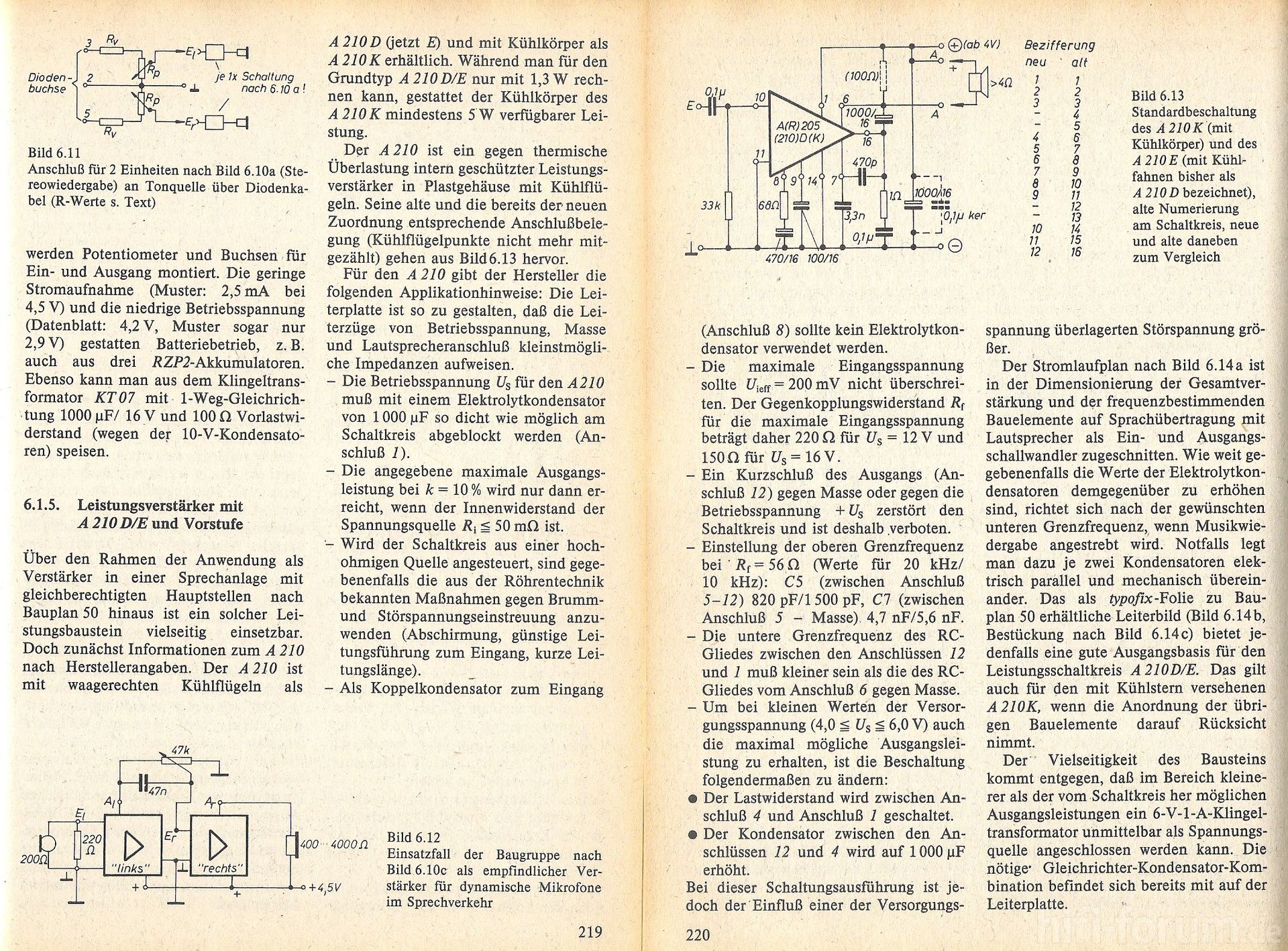
AC-DC 5V 700mA 3.5W Precision Buck Converter AC 220v to 5v DC step down Transformer power supply module for Arduino
2PCS Ultra-small LM2596 power supply module DC / DC BUCK 3A adjustable buck module regulator ultra LM2596S 24V switch 12V 5V 3V

LM2596S Step-down DC-DC Buck Converter mit 3-stelliger Digitalanzeige

Produktbeschreibungen
Parameter:
Eingangsspannung: 4-40V (wir empfehlen Ihnen, Marge zu verlassen)
Ausgangsspannung: 3.3-24V
Ausgangsstrom: 3 Max (bitte verbessern Kühlung beiandgt; 2 A)
Die Ausgangsspannung voreingestellte Auflösung: 0.1V
Spannungsprüfung Genauigkeit: +/- (1% + 2 Stellen)
Wiring Anschluss:
(mit Terminal und für die drahtbonden Verdrahtung Punkt)
Vin +: VIN + verbinden, um ihre positive
vin-: vin- verbinden, um ihre negative
VOUT positive +: Vout + verbinden, um ihre Ausgabe
vout-: vout- verbinden, um ihre Ausgabe negative
Mini Buck Step Down Converter DC-DC 1.2V 2.5V 3V 3.3V 5V Power Supply Module
.jpg)
Version 4:
1.Model: AMS1117-3.3V
2.Input voltage: DC 4.75V-8V (The input voltage must be over 1V above the output voltage)
3.Output voltage: DC 3.3V/800mA (The load current can not exceed 800mA)
4.PCB size: 20mm*10mm
XL6009 DC-DC einstellbarer Step-UP Spannungsregler Power Boost Modul

Beschreibung:
XL6009 Chip-Modul verwendet High- Qualität, hohe Effizienz (bis 94 %), geringer Wärme. Es kann ohne Kühlers in 15W arbeiten, oder mit Kühler in 20w.
Technische Daten:
Abmessungen (L x B x H): Ca. 43 x 21 x 14mm (mit Potentiometer)
Eingangsspannung: 3V - 32V
Ausgangsspannung: 5V - 40V (einstellbar)
Ausgangsstrom: Nennstrom 2A, 4A max (zusätzlicher Kühlkörper erforderlich)
Wirkungsgrad: Bis zu 94%
Potentiometer Einstellbereich: im Uhrzeigersinn (Erhöhung), gegen den Uhrzeigersinn (Abnahme)
Schaltfrequenz: 400kHz
Gleichrichter: Non-Synchrongleichrichtung
Modul-Eigenschaften: Nicht isolierte Abwärtsmodul (Buck)
Betriebstemperatur: -40 bis 85 Grad Celsius (Ausgangsleistung 10W oder weniger)
Full Load Temperaturanstieg: 40 Grad Celsius
Laständerung: ±0,5%
Spannungsregelung: ±0,5%
Geschwindigkeit der dynamischen Resonanz: 5% 200uS
Connection Mode: Schweißkonstruktionen sowie Stift kann direkt gelötet werden PCB
Hinweis:
Dieses Modul ist einstellbar Schub -Modul. Um die Ausgangsspannung zu ändern, können Sie das Modul über dem sinkenden blauen einstellbaren
Widerstand anpassen. Die maxiMaße Ausgangsspannung beträgt 40V .
Module über IN - ( Minus-Eingang ) angedeutet, IN + (positive Eingang) , OUT - (negativer Ausgang) , OUT + ( positiver Ausgang) müssen korrekt angeschlossen sein , sonst kann es Schäden am Modul führen.
Sie die Nennausgangsleistung des Moduls nicht überschreiten , zum Beispiel das Modul ( 20W ) kann nicht verwendet werden, um Laptop liefern ( 90W ) zu verwenden. Dieses Modul hat keine Ausgangskurzschlussschutz.
Produktbeschreibungen
Größe:XL6009  |  Farbe:1 Stück
Kleines, leistungsstarkes DC/DC-Wandlermodul mit einstellbarem Spannungsregler (XL6009).
Ideal zur einfachen und universellen Spannungsanpassung für unzählige Anwendungen im Elektronik-Bereich.
Tests auf die Probe :
In: 3V    out: 12V   0.4A   4.8W
in: 5V    out: 12V   0.8A    9.6W
in: 7.4V  out: 12V  1.5A    18W
in: 12V   out: 15V   2A      30W
in: 12V   out: 16V   2A      32W
in: 12V   out: 18V  1.6A    28.8W
in: 12V   out: 19V   1.5A   28.5W
in: 12V   out: 24V   1 A     24W
Perfekt für beispielweise:
High Power LEDs
Arduino Projekte.
Leistungsstarke Spannungsversorgung für da er bis zu 3 Ampere aushält
Leistungsstarke Spannungsglättung bei Schwankungen
Technische Daten:
100% nagelneu
Eingangsspannung: 3,2 V-42V
Ausgangsspannung: 5 V-35V
Maximale Effizienz: 94%
Spannungsregelung: ± 0,5%
Funktions Temperatur -40 bis + 85 °C
Frequenz 400KHz
Maße (LxBxH): 44x21x13 mm
AC 220V 230V to DC 3.3V 5V 9V 12V Step Down Converter Board Power Supply Module
.jpg)
Mini DC-DC 12-24V Zu 5V 3A Step Down Netzteil Modul Spannung Buck Converter einstellbar 97.5% 1,8 V 2,5 V 3,3 V 5V 9V 12V

Spezifikation:
1.Input Spannung: DC 4,5-24V
2.Output Spannung: integration einstellbar und feste ausgangs, zurück seite können wählen fiexd ausgang spannung
3. einstellbar Bereich: 0,8-17V, festen spannung (1,8 V 2,5 V 3,3 V 5V 9V 12V)
4.Output Strom: 3A (max), tatsächlichen eingang 12V ausgang 1,5 A
5. verwandeln Effizienz: 97.5%(max) (6,5 zu 5V 0,7 A)
6. schalter Frequenz: 500KHz
7.Output Welligkeit Welle: 20mV (12V zu 5V 3A) 20m band breite
8.Operating Spannung:-40 Celsius-85 Celsius
9.Output Überspannung Schutz: keine
10. statische Strom: 0,85 MA
11. last Einstellen Rate:± 1%
12. spannung Einstellen Rate:± 0.5%
13. dynamische Antwort Geschwindigkeit: 5% 200uS
14. ausgang Kurzschluss Schutz: ja
15. eingang Umsetzung Schutz: keine
16. ermöglichen die Steuerung: ja
17. anschluss Typ: löten
18. eingang Weg: löten
19. ausgang Weg: löten/pin
20. löten Loch Raum: 2,54mm