GSM Modul
Inhaltsverzeichnis
GPS
https://www.cooking-hacks.com/projects/arduino-realtime-gps-gprs-vehicle-tracking/
https://www.cooking-hacks.com/documentation/tutorials/geolocation-tracker-gprs-gps-geoposition-sim908-arduino-raspberry-pi/
SIM900
https://www.cooking-hacks.com/gprs-quadband-module-sim900-for-arduino
https://www.cooking-hacks.com/documentation/tutorials/gprs-gsm-quadband-module-arduino-raspberry-pi-tutorial-sim-900/
SIM908

https://www.cooking-hacks.com/gprs-gps-quadband-module-for-arduino-sim908
https://www.cooking-hacks.com/documentation/tutorials/geolocation-tracker-gprs-gps-geoposition-sim908-arduino-raspberry-pi/
https://www.cooking-hacks.com/gprs-gps-quadband-module-for-arduino-sim908
https://www.cooking-hacks.com/gprs-gps-quadband-shield-for-raspberry-pi-sim908
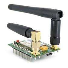
SIM800L
Smallest SIM800L GPRS GSM Module MicroSIM Card Core BOard Quad-band TTL Serial Port
Description:
Chip: SIM800L
Voltage: 3.7-4.2V
Support networks: China Mobile, China Unicom and global quad-band network
Module size: 2.5cmx2.3cm
TTL serial port for serial port, you can link directly to the microcontroller. No need MAX232
Power module automatically boot, homing network
Onboard signal lights all the way . It flashes slowly when there is a signal, it flashes quickly when there is  no signal
http://www.ayomaonline.com/programming/quickstart-sim800-sim800l-with-arduino/
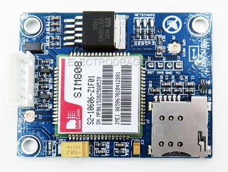
SIM808
Description:
1.Three power input interface: DC044 interface and V_IN and a lithium battery interface.
Note that: The range of DC044 and the V_IN pin voltage input is 5 - 26V, when use the 5V as the power, be sure that the power supply  can provide 2A current. The range of voltage of Lithium battery input power is 3.5 - 4.2V.
2. Switch: It is used to open / close the input power supply for the module. When in use, please confirm the toggle switched to the OPEN state (near the board inside).
3. SMA antenna interface: there is a GSM antenna interface, a GPS antenna interface onboard and a BT antenna interface.
4. Start button: When the board is power on, the LED (PWR) will light up. After a long press (about 2 second) on this button, the other three LEDs will be light. And one of them starts to flash; this suggests that SIM808 is beginning to work now. When the power supply, GSM and GPS antenna and SIM card are connected to the module correctly, the LED will be flash slowly (3Second de 1second light), that indicates that the module is registered to the network, and you can make a call or do something else.
5. TTL serial interface: a TTL level interface. Notice that: The pin of VMCU is used to control the high level of TTL UART, so as to realize to match between 1.25V/3.3V /5V systems. For example, if you want to use the 51 MCU to control this board, the pin of VMCU should be connected the DC5V. And if use the STM32 MCU, the pin of VMCU should be connected the DC3.3V. The pins of RXD is the RXD of SIM808 and the pins of TXD is the TXD of SIM808. The pin of V_IN can connect the Power, the function of this pin has the same function of DC044.
6. USB interface: This interface is just use to update the firmware of SIM808 module.
Operation Description:
1. Preparation:
SIM808 SHIELD
DC9V adapter
USB-TTL module or other tools.
PC software
2. Hardware configurations
2.1 Connect the USB-TTL to the UART interface

USB-TTL  SIM808
TXD       RXD
RXD       TXD
GND       GND
2.2 Insert the valid SIM card to the SIMCARD holder.
2.3 Connect the GPS antenna and GSM antenna to the board
   Connect the power adapter to the DC044 Interface
2.4 Change the Switch
2.6 Press the POWKEY button for 2 second, the SIM808 module will work and the other 3 LEDs will light.
Document Link:https://www.adrive.com/public/P7QRkq/FZ1735-SIM808%20%E5%A4%A7V3.1.rar
http://simcom.ee/modules/gsm-gprs-gnss/sim808/
http://simcom.ee/documents/?dir=SIM808

https://www.adafruit.com/product/2637
https://learn.adafruit.com/adafruit-fona-808-cellular-plus-gps-breakout/wiring-to-usb

http://www.electrodragon.com/w/SIM808_Dev._Board
http://simcomm2m.com/En/module/detail.aspx?id=137
http://www.elecrow.com/wiki/index.php?title=SIM808_GPRS/GSM%2BGPS_Shield_v1.1

https://www.itead.cc/wiki/SIM808_GSM/GPRS/GPS_Module
https://github.com/itead/ITEADLIB_Arduino_SIMCom
Arduino Librarys
https://github.com/vshymanskyy/TinyGSM
https://www.arduino.cc/en/Reference/GSM
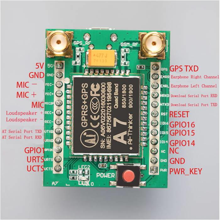
GSM A7
https://github.com/SensorsIot/A6-GSM-Module
GPRS module GSM module A7 \ SMS \ Speech \ board \ wireless data Transmission
http://www.icstation.com/gprsgpsgsm-module-development-board-support-85090018001900mhz-p-9947.html
https://www.elecrow.com/wiki/index.php?title=A7_GPRS%2BGSM%2BGPS_Shield
https://raymondtunning.wordpress.com/2016/05/31/a6-gsmgprs-module-pinout-and-data/
https://github.com/SensorsIot/A6-GSM-Module
AT+GPS=1
AT+GPSRD=1
AT+AGPS=1

AT+GPS=0
AT+AGPS=0
AT+GPSRD=0
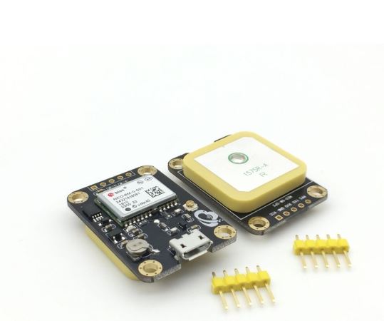
GPS NEO6M
GPS module micro USB NEO-6M UBLOX satellite positioning 51 single-chip for Arduino STM32 routines
Module parameters 1. Voltage
Input voltage: 3.3-5.5V
Power consumption
Normal mode: 50 mA
Power Saving Mode: 30 mA
2. Temperature
Operating Temperature -40 ° C to + 85 ° C
Storage temperature -55 ° C to + 100 ° C
3. Pin descriptions and electrical connections
Module pin
1 VCC  Power input pin 3.3-5.5V
2 GND  Power ground
3 RXD  Module serial port to receive the foot - then single-chip serial port TXD sent
4 TXD  Module serial send pin - then the microcontroller serial RXD reception
5 PPS  Clock pulse output pin
Module PPS feet connected to the red LED lights
On: Normal operation, but not positioned. Blinking: The positioning was successful
4. Baud rate
The default baud rate for the module is 9600
5. Characteristic parameters
Module comes with ceramic antenna, another IPEX interface can be connected to other active antenna
Module increases the RF amplifier circuit, is conducive to speed up the search star
The module comes with rechargeable battery backup, you can power-down to maintain ephemeris data
Module compatible with 3.3V / 5V level, easy to connect a variety of microcontroller systems
Eigene Seiten
http://www.mprojekte.de/geopos/demo_sim908.php
http://192.168.0.181:18082/
http://www.mprojekte.de/gps/gps.php
http://www.mprojekte.de/gps/i-am-here.php
http://www.mprojekte.de/gps/track.php
http://www.mprojekte.de/gps/i-am-here-position.php
Videos
GSM TCP/IP - How to send Data to Server using SIM900A
https://www.youtube.com/watch?v=X-DuA7THATg

Arduino + GSM (HTTP GET requests)
https://www.youtube.com/watch?v=cpgQOmQwUL8
AT Commands
http://www.electrodragon.com/w/AT_Commands
SIMCOM SIM800
http://www.electrodragon.com/w/SIMCOM_AT_Commands
T68 AT Test Commands
http://www.anotherurl.com/library/at_test.htm
ATOI
ATOI
Ai Thinker Co.LTD
A7
V03.03.20161229019H03
OK
AT+CPIN
AT+CPIN=xxx
Tools
SocketTest
http://sockettest.sourceforge.net/
AT Command tester
http://m2msupport.net/m2msupport/forums/forum/at-command-tester/
Code
https://www.tweaking4all.com/hardware/arduino/arduino-ethernet-data-push/
http://blog.protoneer.co.nz/arduino-http-post-requests/
https://forum.arduino.cc/index.php?topic=155218.0
http://forum.arduino.cc/index.php?topic=165680.0
http://forum.arduino.cc/index.php?topic=116867.0
http://forum.arduino.cc/index.php?topic=160470.0
http://stackoverflow.com/questions/13221036/arduino-ethernet-shield-http-1-1-400-bad-request
http://forum.arduino.cc/index.php?topic=429758.0
http://forum.arduino.cc/index.php?topic=402531.0
Daten hochladen mit POST
const char server[] = "http://www.mprojekte.de";
const char host[]="www.mprojekte.de";
String Data ="CCID='" + modem.SimCCID + "'&" + "IMEI='" +modem.SimIMEI + "'&" + "IP='" + IP + "' HTTP/1.1\r\n" ;
if (client.connect(server, 80)) {
Serial.println("-> Connected");
// Make a HTTP request:
//client.print( "POST /KFZ_Daten/add.php?Name=Thomas HTTP/1.0\r\n");
//client.print( "POST /KFZ_Daten/add_data.php?");
client.print( "POST /KFZ_Daten/db.php?");
//client.print("Name=Thomas HTTP/1.0\r\n");
//client.print( "serial=288884820500006X&temperature=12.5 HTTP/1.1\r\n");
client.print( Data);
//client.print( "Host:www.mprojekte.de\r\n" );
client.print( "Host: " );
client.println(host);
client.print( "Connection: close\r\n" );
client.println();
//client.stop();
}
else {
// you didn't get a connection to the server:
Serial.println("--> connection failed/n");
}
client.stop();
SerialMon.println("Server disconnected");


